Arduino Playstation 2 Controller Library Troubleshooting Guide

Posted in Arduino Libraries by Bill
27 Mar 2011
Arduino Playstation 2 Controller Library Troubleshooting Guide

Ok, if you are here, you are having trouble getting your Arduino talking to your PlayStation 2 Controller via my Handy Dandy PS2X Library. Well, never fear, I stand by my leet coding abilities (Ha! who am I kidding? Really though, the library works, there’s tons of examples using it.) and I’m here to help. The problem is there’s not much I can really do unless you live near North Florida and want to come pay me a visit. It’s hard giving help over the internet! But maybe I can guide you in the right direction with this troubleshooting guide.

I’ll walk you through some debugging steps, and you should follow through with me with DEBUG off until I tell you to enable it and using the example sketch unmodified. In-between attempts, power off the Arduino and controller for 10 seconds before testing it again.  I’ll bold the quick steps if you want to skim through.

A little background first. I have not personally reverse engineered the communications protocol a PS2 controller uses. That has been done by a few other cool guys like this one.  I used what they reported in writing the PS2X library. As far as I know Sony has never official published the communications protocol to the public, so reverse engineering efforts is all we have to go on. This has lead to a few problems; for example some controllers just don’t behave like others. From the various sources around the web, the best chance of success comes from using ‘Official’ Sony controllers, and not the cheap knock-offs, 3rd  party controllers. There’s also some links with wireless controllers not working well either. Personally I have tried a wired Sony controller, and a few wireless Guitar Hero Controllers all with success, powered at 5V and no resistors.

Therefore the first thing to consider is what controller are you using? Can you try another brand, model?

Ok, now that we are past history of controllers, I’ll tell you this: 90% of the problems people have end up being related to wiring. I can’t look at your setup, so you are going to have to use your best judgment. Does the wiring look sound? Controller wires are thin and small and tend to break easily. During prototyping, I cut the ends off my wired controllers, stripped 1/4″ insulation off and heavily tinned the wires to create solid ‘pins’ that could be pushed into the female pinheader on the Arduino. This method worked, but was fragile. Later on I bought a few $5 PS2 controller extension cables and cut off the female receptacle end. I soldered the wires from the plug to PCB board and that worked well also.


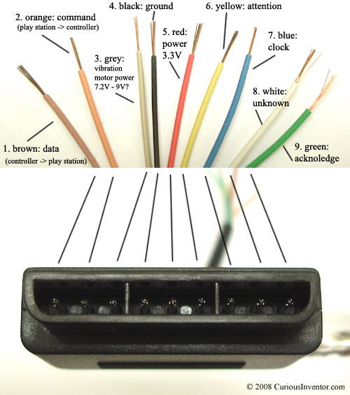
Don’t trust the color scheme on the wiring picture. It can vary! Instead, use a voltmeter and test continuity between pin positions in the connector and the bare wires. I’ve had a few people report odd color schemes, and a few not realize what end of the connector they were looking at and got the wiring completely backwards. A quick check is to power up the controller, and pushing the ‘Analog’ button. Either the LED should have been on when it powered up, or it should light up when you press the button. If not, the controller isn’t getting power and you probably have the wiring reversed.

Alright, so you trust the wiring job, what next?

There are discussions over whether or not the controllers are tolerant of 5V logic. I’ve never had one burn out, so I believe they can handle “receiving’ 5V, but they still won’t ‘send’ 5V to the Arduino. It seems to me the one fix that seems to work the most is adding a 10k resistor between DATA (brown wire, or pin 1 on the controller port) and VCC (try both 3.3V and 5V in that order) on the Arduino.

This will help ‘pull-up’ the data line. Also there’s disagreement on what voltage to use to power the controller. A PlayStation powers the controller at 3.4V. I have always powered my controllers at 5V and had no problems, but it is risky. Controllers are so cheap on ebay though, why not try it? Try different voltages for power, switch between 3.3V and 5V, and for each voltage try it with and without the pull-up resistor on the DATA line .

One person claimed his controller wouldn’t work without level shifting all his wires, which means he just added resistors inbetween the controller’s pins and the Arduino.

The numbers he reported success with is as follow:

  1. 5V = 180 ohm, voltage drop of 1.85V (3.15v to the controller)
  2. ATT = 5.6K ohm, voltage drop of 1.08V (3.92 to the controller)
  3. CLK = 5.6K ohm, voltage drop of 1.15V (3.85 to the controller)
  4. CMD = 860K ohm, voltage drop of 1.39V (3.61 to the controller)

so you can give that a try as well. Though really, ignore the resistor on 5V and just connect the red power wire to 3.3V.

Some people report issues using pin 13 on the Arduino for CLK. Try moving the CLK line to another pin, and editing the example sketch to match.

If you have gotten this far and still no luck, you might just be out of luck. Controllers can go bad and some people just aren’t any good at wiring. But, there’s one more thing we can try messing with.

There’s a value in the ‘PS2X_lib.h’ file that governs the speed of the bus to the controller. It’s called ‘CTRL_CLK’ and you can find it by looking for this line:

#define CTRL_CLK        4

The PlayStation 2 talks to its controllers at 500kHz, or a value of ‘2’ in my library. Arduino tends to have issues setting a value that low, so by default I have it set at 4. You can try using 2 instead, and I’d also try using some higher number for a slower bus speed. Go from 2-20 and even 200 to see if you can get the controller talking. Remember to save the .h file every time you edit it, and re-compile the sketch.

Still no luck? Man you are killing me. I’ve dropped all my suggestions into this guide, so there’s not much else I can say even if you ask really nicely. Florida is nice year round, so feel free to come visit me and I will help you in person. Otherwise, you can try to enable debug. It won’t really help diagnosing wiring problems (or bad controllers) because all you will see is all FF’s or 0’s. But if you are getting some values, they may be something else going on. Drop the output in the Support Forum and I’ll see if I can help.

My last fleeting thoughts include removing the checks in the example. At the end of the setup function (after the switch statement and before the closing curly bracket ‘}’ ), add the following code:

error = 0;

type = 1;

This will bypass the error checking and run the code anyway. What do you get? Try pressing reset on the Arduino without disconnecting the controller. Anything?

Still need help?

Use the Support Forum to ask for help. Please don’t use the comments below.

Share

Warning: count(): Parameter must be an array or an object that implements Countable in /homepages/46/d285670699/htdocs/bill/wp-includes/comment.php on line 879
  1. 180 Comments.

    • AbdulrahmanNo Gravatar says:

      Hello ! , Thank you !!! my ultra cheap wireless ps2 controller worked
      after i bypassed the error check
      by adding this to the end of the setup :
      error = 0;

      type = 1;

      the wireless device needs a delay to detect the receiver when powered up but the code checks for a joystick before this happens , bypassing error check solved it for me .

    • EBruneNo Gravatar says:

      Hello Bill,

      I am building a XBee PS2 controller am having a weird issue. My controller seems to only be responding to L3 and R3 toggles. The rest of the channels don’t respond at all but I do get some random channels firing without any user input. Any thoughts? I feel like it could be a bad dualshock as it was given to me by a friend that had it lying around. Here is what I was receiving in debug:

      UT:IN Configure
      1:FF 43:73 0:5A 1:FF 0:3F
      OUT:IN Configure
      1:FF 44:F3 0:5A 1:0 3:0 0:0 0:0 0:0 0:0
      OUT:IN Configure
      1:FF 43:F3 0:5A 0:0 5A:0 5A:0 5A:0 5A:0 5A:0
      OUT:IN
      1:FF 42:73 0:5A 0:FF 0:3F 0:83 0:7E 0:7B 0:7E 0:0 0:0 0:0 0:0 0:0 0:0 0:0 0:0 0:0 0:0 0:0 0:0
      Found Controller, configured successful
      Try out all the buttons, X will vibrate the controller, faster as you press harder;
      holding L1 or R1 will print out the analog stick values.
      Go to http://www.billporter.info for updates and to report bugs.
      DualShock Controller Found
      OUT:IN
      1:FF 42:73 0:5A 0:FF 0:3F 0:83 0:7E 0:7B 0:7E 0:0 0:0 0:0 0:0 0:0 0:0 0:0 0:0 0:0 0:0 0:0 0:0
      OUT:IN
      1:FF 42:73 0:5A 0:FF 0:3F 0:83 0:7E 0:7B 0:7E 0:0 0:0 0:0 0:0 0:0 0:0 0:0 0:0 0:0 0:0 0:0 0:0

    • Salman ShaikhNo Gravatar says:

      Hello,
      I want to use the analog joysticks for driving my robot but initial readings i.e., the center readings of ps2x.Analog(PSS_LY) changes everytime i move the joystick…
      I would be highly obligued by your support…

      • AndyNo Gravatar says:

        I’ve had that problem too, but that is the fault of the PS2 controller, not the library’s.
        The stick doesn’t always jump back to the original position when let go.
        I solved the problem in my program by creating a margin around the ‘center’ of 10 so that the stick would always be in the center position when untouched.

    • Tim-TNo Gravatar says:

      Great work bill and others….

      quick question.. on my ps2 dualshock 2 controller i had to change the CTRL_CLK to 15 and it worked everytime.

      i notice that the hardness doesnt show up when pressing the pad buttons. its always 0. if i turn on debug then i can see the values change.

      thoughts?

      thanks

      Tim

    • AndyNo Gravatar says:

      The CLK line being on Pin 13 and disturbing the controller is ABSOLUTELY TRUE. I urge everyone who has their CLK line on Pin 13 to change it!

    • AndyNo Gravatar says:

      I’ve had a strange problem lately, which I’ve fixed now:

      If I used
      error = ps2x.config_gamepad(10,11,12,13, true, true);
      in my program, the controller would turn on, but soon after the ‘ANALOG’ light would turn off and the controller wouldn’t respond anymore.

      I found out that I could solve that problem by using
      error = ps2x.config_gamepad(10,11,12,13, false, true);
      ps2x.enablePressures();

      Why does this help? Any ideas Bill?

      • RobinNo Gravatar says:

        Hello !
        my ps2 dualshock 2 controller appeared
        error = 0 or 3
        type = 1
        that’s what I want!
        but today the ps2 dualshock 2 controller abruptly appears
        error = 1
        type = 0
        I can’t figure out the mistake,
        what’s the problem and how cloud I solve this?
        thanks!

    • VDLNo Gravatar says:

      Help please. If I have a ps2-usb adapter, as I have to send signal from the TX and RX?

      http://imageshack.us/photo/my-images/842/20130503135600.jpg/

    • DylNo Gravatar says:

      Sweet… Took a lil debugging as the controller is from a PSOne that i got at a thrift store for 5bucks with an old rotary telephone… Thanks for this wicked library… Nice Job… High fives and happy dance…

    • shaileshNo Gravatar says:

      Which arduino board (model:duemilanove or pro mini or leonardo) for interfacing ps2 controller……..Please reply ASAP

    • BlueNo Gravatar says:

      Unable to get this to work, I’m sure I’m just missing something really obvious. I’ve tried almost all of the solutions on the troubleshooting page, minus shifting all of the wires. Powered through 5v, 3.3v, tried a diff pin for clock, changed define CTRL_CLK to 2-20,200,8, added a 10K pull-up to data, checked wiring(this might be the problem, I wired this controller a while back without the best tools, so I’m going to go rewire it again).

      Current output:
      OUT:IN
      1:0 42:0 0:0 0:0 0:0 0:0 0:0 0:0 0:0 0:0 0:0 0:0 0:0 0:0 0:0 0:0 0:0 0:0 0:0 0:0 0:0
      OUT:IN
      1:0 42:0 0:0 0:0 0:0 0:0 0:0 0:0 0:0 0:0 0:0 0:0 0:0 0:0 0:0 0:0 0:0 0:0 0:0 0:0 0:0
      Controller mode not matched or no controller found
      Expected 0x41 or 0x73, got 0
      No controller found…etc

      But its 4:53AM, and I think it’s time for a nap.

    • AntonioNo Gravatar says:

      Hi! I need help!

      After several days I get to my desperation for something “simple” that is already done.

      I read that you have to put a 10K resistor between VCC (5v) and DATA. I put it in the serial but I get this message:

      Quote

      Refusing to enter Pressures Controller mode, May not support it.
      DualShock Controller Found

      This happens to me with a remote NOT SONY. If I connect SONY command get another error:

      Quote

      Controller not found, check wiring, see readme.txt to enable debug. http://www.billporter.info visit for troubleshooting tips
      Unknown type Controller

      Wireless receiver power knob I fed Ps2 3.3v from arduino itself.

      Sure it’s easy for you, but I’m going crazy to detect the remote!

      I hope your help.

      Greetings!

      Sorry for my English. 😛

    • AntonioNo Gravatar says:

      Guys! I need help!

      After several days I get to my desperation for something “simple” that is already done.

      I read that you have to put a 10K resistor between VCC (5v) and DATA. I put it in the serial but I get this message:

      Quote

      Refusing to enter Pressures Controller mode, May not support it.
      DualShock Controller Found

      This happens to me with a remote NOT SONY. If I connect SONY command get another error:

      Quote

      Controller not found, check wiring, see readme.txt to enable debug. http://www.billporter.info visit for troubleshooting tips
      Unknown type Controller

      Wireless receiver power knob I fed Ps2 3.3v from arduino itself.

      Sure it’s easy for you, but I’m going crazy to detect the remote!

      I hope your help.

      Greetings!

      Sorry for my English 😛

    • RodrigoNo Gravatar says:

      Dear Bill,

      My name is Rodrigo, I live in Brazil. First of all I would like to thank you for your collaboration. I mean I have used your library and followed your tutorial and never had problems. Already used the control of PS1 and PS2 original and parallel with good results. I’m working on a robot, where I intend to link through the APC220 radio module, so I made some changes in your program so that it sends the state of the control buttons in continuous time, and create a string of 53 positions and then fill it sends the data as follows:

      * 0, 0, 000, 000, 000, 000, 0, 0, 0, 0, 0, 0, 0, 0, 128, 128, 128, 128 #

      Once the code is mature enough, I’ll send it to you to evaluate ..

      Anyway, I guess my question to you is very simple:

      1) What is the green wire (acknoledge)?
      2) I’m using a resistor “Pull-Up” between DC ‘5V’ and ‘Data’. Because the analog mode is always active?

      Thanks and sorry my bad english. 🙂

      []’s

      Rodrigo

    • RodrigoNo Gravatar says:

      Dear Bill,

      My name is Rodrigo, I live in Brazil. First of all I would like to thank you for your collaboration. I mean I have used your library and followed your tutorial and never had problems. Already used the control of PS1 and PS2 original and parallel with good results. I’m working on a robot, where I intend to link through the APC220 radio module, so I made some changes in your program so that it sends the state of the control buttons in continuous time, and create a string of 53 positions and then fill it sends the data as follows:

      * 0, 0, 000, 000, 000, 000, 0, 0, 0, 0, 0, 0, 0, 0, 128, 128, 128, 128 #

      Once the code is mature enough, I’ll send it to you to evaluate ..

      Anyway, I guess my question to you is very simple:

      1) What is the green wire (acknoledge)?
      2) I’m using a resistor “Pull-Up” between DC ‘5V’ and ‘Data’. Because the analog mode is always active?

      Thanks and sorry my bad english. 🙂

      []’s

      Rodrigo Carpe

    • AshutoshNo Gravatar says:

      Hi, can i please get the wiring or fritzing circuit diagram for where to connect the pins on my arduino?
      Thanks in advance!

Leave a Reply

This site uses Akismet to reduce spam. Learn how your comment data is processed.