How to Add Multiple Serial Connections to your Custom Arduino Board or What Those 1k Resistors Do

Posted in Tutorials by Bill
26 Jun 2011
How to Add Multiple Serial Connections to your Custom Arduino Board or What Those 1k Resistors Do

A friend of mine is working on his own custom Arduino powered LCD backpack and asked me to look at his design.  I noticed it had a header for the all to familiar FTDI board to program the Arduino and a separate header for power and data connection. Both headers had the ATMega’s UART pins broken out. The problem with this design is it then requires the user to disconnect whatever they have connected to the second set of UART pins whenever they want to attach the FTDI board to upload a new sketch. With a few more passive parts, he could eliminate that need. This is a quick tutorial for beginners looking to roll their own Ardunio boards and may have missed this very easy and time saving design trick.

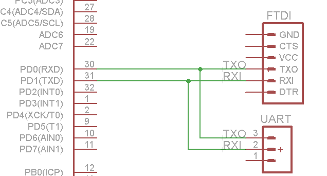
Let’s take a look at his effective schematic. I’ve only drawn the UART lines to keep things simple.

The problem here is if two different devices (like an FTDI and another Arduino) are both trying to drive the TXO line something will burn out or just not work. It would be like shorting 5V to GND, bad things will happen. So if a user wanted to reflash the onboard AVR chip with an FTDI, they would have to disconnect whatever was plugged into the other UART header.

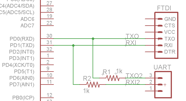
But if you add one or two resistors you can avoid that. Let’s take a look at this design.

Ok, so now we have two 1k resistors seperating the second UART header from the AVR and FTDI header. But what are they doing?

Well, lets think about it. If the FTDI is plugged in and sending a logic 1 (or HIGH) while a second device is sending a 0 (or LOW) it will create a voltage drop across R1. If we are dealing with a 5V system, about 5mA will flow through R1 according to Ohm’s Law V=IR. 5mA is a safe low current for most devices to handle and the opposing devices won’t harm each other. But the ATMega will only ‘hear’ the device that is on the same side of the resistor.

Maybe a simulation (via Falstad) will make things a little clear. Here’s our new design. Let’s say RED represents a logic LOW and GREEN is logic HIGH. I am using two pulse generators to represent data being transmitted from 2 UARTs. Lets see what the ATMega sees when two devices are both trying to transmit at once.


So the resistor gives the FTDI chip ‘priority’ over whatever is connected to the second UART header. If there is no FTDI plugged in, the ATMega will ‘hear’ whatever is coming in on the second UART header. This is because the ATMega’s RX pin is effectivly a open circuit and draws no current. No current means no voltage drop across the resistor and the signal gets through unaffected.

This means you are safe to flash new sketches without unplugging anything. Well, safe data wise. There are concerns about the FTDI’s onboard power VCC pin fighting with whatever power supply may be running on your widget, but that’s another tutorial.

This trick is how the regular Arduino board allows you to access with ATMega’s UART pins without fighting the onboard FTDI chip. Let’s take a look at it’s schematic:

There you see the ‘prioritizing’ resistors on the UART lines between the FTDI (or it’s replacement) and the main ATMega. This mean if anything is plugged into the UART pins (digital pins 0 and 1) it will ‘override’ whatever the FTDI is transmitting.

So there you have it. Two resistors in your design can make it easier and safer to upload new code.

 

Share

Trackbacks / Pingbacks

  1. Circuit design for multiple UART connections - Hack a Day
  2. Finally got XBee, BT Serial, and menu system working… oh and Nunchucks too! | Mecharobotics's Blog

Warning: count(): Parameter must be an array or an object that implements Countable in /homepages/46/d285670699/htdocs/bill/wp-includes/comment.php on line 879
  1. 42 Comments.

    • LarryNo Gravatar says:

      Very good article, useful and accurate. The only suggestion I would make would be to change your every use of the word ‘UART’ to ‘serial data’.

      UART has a very specific meaning, universal asynchronous receiver transmitter. It is a name given to a hardware (or software) function that converts serial to parallel and parallel to serial data streams at a specific baudrate and adding start/stop/and optionally parity bits. What you are describing (very well I might add) is the safe way to wire up multiple serial data devices that need to share a single serial data link.

      • BillNo Gravatar says:

        You are right Larry. ‘Serial header’ is a better description. Though to save me from having to regenerate the pictures and video I’m going to leave most of the references as UART for now.

    • […] Porter] has a tip for designing circuits that have multiple connections to a single microcontroller UART. This stemmed from a review of a friend’s circuit design that used the UART in the project, […]

    • techspyNo Gravatar says:

      Great info. In my case I have a device that communicates through an XBee link via an explorer board. There is another device onboard that uses the same din/dout. Do you think this would work in this case?

      • BillNo Gravatar says:

        Hi techspy,

        Hmm, you might have to be more detailed. What is your other device?

        This method just lets you physically have two devices wired, but only one will talk to your Arduino. One that one is removed, then the second device can talk. It’s kinda like a selector switch.

        • techspyNo Gravatar says:

          Ah ok. No I am talking about 2 devices communication with the arduino at the same time. (Not actually an arduino but a device that passes serial info) To be specific, a Mikrokopter flight control board that outputs flight data to an on screen display and to an XBee that then routes the info to a PC that shows the same data.

          • MobilewillNo Gravatar says:

            Why don’t you use a the softserial library. I use that for my LCD and Voice shields. Then the Serial link is freed up for the xbee/sketch upload using the above design. I am going to try adding the resistors to my project this weekend. Should speed up development a lot. Right now I have to hit the switch on the xbee to disconnect it from the serial line, really annoying. So glad Hack-a-day posted this. I take it regular 1k resistors will work? Hack-a-day mention current limiting, is that anything special?

            • BillNo Gravatar says:

              Regular 1k will work. Nothing special about the current limiting, they were just referring to the fact a resistor will stop destructive current from hurting your devices.

            • LensdigitalNo Gravatar says:

              As far as SoftwareSerial, it’s very picky and doesn’t really work with other Atmel chips like ATMega1284p. And it’s very picky about which ports are “allowed” to be software serials. Bill’s suggestion is awesome and elegant! 🙂 I can’t wait to try it out on my 1284p!

    • Phot says:

      You actually only need one resistor. The resistor on the TXD line is not needed

      • BillNo Gravatar says:

        I suggest a resistor on both in case the ‘usually connected’ device is something other then a serial port, like general IO input holding both lines low or high.

    • MobileWillNo Gravatar says:

      I take it this doesn’t work on Arduino such as the Mega and the Uno where the FTDI is always connected? Or is it not connected when a USB is not plugged in?

      Some other people mentioned using a AND gate or a Mux. I will have to look into those.

      • BillNo Gravatar says:

        Like I said in the tutorial, the retail Arduino boards already use this trick, just in reverse. Whatever is plugged into Digital pins 0 and 1 will override the onboard FTDI.

        What are you trying to do?

        • MobileWillNo Gravatar says:

          I have a Arduino Mega and Sparkfun Xbee shield. I would like to be able to upload code without flipping the switch on the xbee shield (switch is for changing tx/tx pins)

    • ConstantinNo Gravatar says:

      Hi Bill,

      Many thanks for the write-up, it may have saved me some hair (in advance). However, I still have a question: Let’s say I have two Arduino MCU’s that are connected to each other via their hardware serial connections (i.e. D0 and D1, the TX-RX on pins).

      If I still want to use the FTDI header for programming, I presume that the 1k resistors you mention above should be placed in-line to the above RX-TX connections *between* the two Arduinos, right?

      Since I have some pins left over, I could also go the new soft serial approach. Which approach (hardware serial + resistors, or newsoftserial) is better?

      Additionally, would the type of oscillator make any difference on the ability of the arduinos to talk to each other? I plan on clocking both at 20MHz using ceramic oscillators. Both also run on 3.3V, i.e. no VCC difference to contend with.

      Many thanks for any insights you can offer, Constantin

      • ConstantinNo Gravatar says:

        Ooops, never mind the 20MHz @ 3.3V reference. For obvious reasons (RTFM) that won’t work. I guess I either have to live with 8MHz, switch to a 5V architecture, or push the chip beyond its intended specification to do 16MHz as JeeNodes do…

      • BillNo Gravatar says:

        Hi Constantin,

        Do you want to be able to program both through their serial ports with the FTDI?

        Just one would be easy, resistors inline, and just put the FTDI port on the same side of the resistor as the AVR core you want to program. If you want to be able to program both, that’s a bit trickier, but can be done. I wouldn’t resort to processor intensive software serial libraries just to leave the hardware port open for programming, that’s overkill.

        You could have two FTDI ports on board, one for either core, and on either side of the resistors, or we could get into selector switches.

        • ConstantinNo Gravatar says:

          Hi Bill,

          Thanks for the reply. I am planning on having two FTDIs, i.e. one for each MCU. As I think you just suggested, I connected each FTDI to the “inside” of each resistor (there are two 1k resistors, one for each TX line).

          Just got your second reply… Sparkfun is actually kosher re: Atmel specs, it’s the Jeelabs of the world that ignore them (and FWIW, Grumpy Mike took a dim view of this in the Arduino forums). Anyhow, to run the chips at 20MHz, I resorted to going back to 5V for the MCUs and using a voltage translator chip to bring the MOSI/SCK/SS SPI levels down to 3.3V for the two 3.3V-only devices I have on the board. Thankfully, an Arduino running at 5V can read the 3.3V MISO reply without modification.

          Like you, I really like the ability to read the data going back and forth between the Arduinos. While I may use an battery-backed RAM for accumulated data storage (I2C on the DS3232) a few bytes here and there is nothing compared to the amount of data that will stream between these arduinos.

          Interestingly, the Atmel datasheet suggests that 250kBPS speeds should deliver 0 error at 20MHz. Time will tell. Thanks again for your work on the Arduino platform and the thoughtful responses.

          • BillNo Gravatar says:

            No, Sparkfun is guilty too on their OpenLogger at least.

            And be careful assuming 3.3V to 5V will work, this is actually one of my pet peeves. Check the spec sheets for both items. For example, all the Xbee carrier boards lie when they say they are 100% 5V logic compatible because there is a 0.2V margin between the AVR’s required min input HIGH and the Xbee’s guaranteed output HIGH. And we have had problems with this over at SOR.

            I recently designed a 5V board with a 3.3V SD card slot, and I shifted up to 5V just to be safe. Only requires a few parts.

            • ConstantinNo Gravatar says:

              Oh dear. Sparkfun too, I have the Openlogger… I guess I shouldn’t use it in hot places!

              I hope I’ll be OK re: the 3.3V issue, the Adafruit SD card reader eschews the use of a translator going from the SD card to the Arduino.

              I spent the better part of a day looking at various “bidirectional” translators, some of which don’t even need a directional signal. That would be nifty, if only these chips came in packages that human beings can hope to solder. What approach do you suggest going from 3.3V to 5V?

            • BillNo Gravatar says:

              Actually, I found this white paper on using a single mosfet to create a bidirectional bridge between voltage levels. No expensive chips necessary. I have successfully tested it in shifting an Xbee out to a 5V AVR, and will shortly be testing it on a SD card as well, though both only needed to be one way.

              It’s quite a handy trick and I don’t think very well know in the DIY community, so I plan on doing a new blog post write-up shortly.

              Does adafruit say why using a transistor is bad?

    • ConstantinNo Gravatar says:

      I don’t know what the issues are at adafruit, but she does maintain a forum, it may be the best place to ask. My guess is it’s a cost question. She’s using a octal level shifter on her microSD breakout board, but not to “up-convert” by toggling the directional pin. See

      https://github.com/adafruit/MicroSD-breakout-board/raw/master/usdbreakout.png

      As for birectional shifting, an approach I considered was the one published on this page,

      http://www.rocketnumbernine.com/2009/04/10/5v-33v-bidirectional-level-converter/

      which may be using the approach you are/were considering. I ended up not using it solely for the reason that installing a single chip (octal converter) to go from high to low was easier to implement than having a row of these mosfets and resistors cluttering the PCB.

      (I presume that a set of three components (10K resistors, BSS138) would be required for each bus, right?)

      On the other hand, if “up-conversion” from 3.3V to 5V on the return signals had been required, I think I would have used this circuit rather than trying to figure out how to properly hit the directional pin on the voltage translator chip.

      Anyhow, thanks again for the help!

    • ConstantinNo Gravatar says:

      Hi Bill,

      Just a quick note for the benefit of those who are not as up to speed on these things as you are.

      When I tried to breadboard this project, I ran into an interesting (for me) snag. Easy Transfer worked great as long as the two pin pairs were directly connected between the 2009 and the Arduino Mini Pro (TX-RX). Both were running off of USB power (in one case a direct USB cable connection, the Mini Pro uses a 5V FTDI cable). They were plugged into the same computer, on adjacent (but presumably separate) USB ports.

      However, once I used the 1k resistors between the two Arduinos, no more reception occurred. Instead, the Mini Pro just sat there, waiting.

      I had to put my thinking hat on and then decided to power the Mini Pro off of the 2009 5V bus and GND them together as well. Additionally, I had to remove the FTDI cable. Now the connection works as expected and Easy Transfer blinks away happily.

      For me, the moral of the story is that if you have two Arduinos, power them with the same 5V and GND power sources or you may run into what I experienced. I suspect differing voltage potentials due to the use of two USB ports, but since I’m not sure why I ran into this problem I thought I’d ask you for help… Cheers!

      • BillNo Gravatar says:

        Constantin,

        While common ground is always good, that wasn’t your problem.

        The FTDI cable will still hold the UART lines high even if you don’t have the serial port open and aren’t sending data. Without the selector resistors, the FTDI was sourcing current. the Arduinos talked to each other, but there was unnecessary current draw on the UART lines and your lucky you didn’t burn something out. When you added the 1k resistors, they did their job in limiting current between competing sources, and the FTDI board took priority over the other Arduino. When you removed the FTDI, there was no more competition and the Arduinos could talk to each other.

    • ConstantinNo Gravatar says:

      weirdness…
      I have two Arduinos sharing the same serial bus and I implemented the 1k resistors as shown above. One of the Arduinos is a mini Pro running on 5V provided by the other arduino (a 2009). The mini Pro is acting as a TX using easy transfer, ie once a second it squirts a burst of data to the other.

      The 1k resistors are not doing their job… Whenever the pro is squirting a data packet, it interrupts/corrupts the data transfer from the computer (via USB and the ftdi chip on the 2009). Should I increase the resistance to 2k to diminish the potential coming from the mini?

      • BillNo Gravatar says:

        2009 meaning a Duemilanova? The Duemilanova already has limit resistor built in. This resistor trick is main for custom rolled boards that don’t have FTDI’s onboard.

        If you draw the schematic out, there’s a 1k between the AVR and the FTDI chip on the Duemilanova. You have added another 1k between the Duemilanova and the pro mini. So when the pro mini tries to hold it high and the FTDI onboard wants to hold it low, you’ve created a voltage divider with two resistors with the AVR on the Duemilanova stuck in the middle. So if you want the board FTDI to have priority, you would have to really increase the resistor between the two Arduino’s so that the ‘voltage diving’ output getting fed into the AVR is within tolerance. A 10k might do it.

        • ConstantinNo Gravatar says:

          I feel like slapping my head… of course!

          FWIW, higher resistance values cause the signal to be dropped i.e. I get no reception on the other end. But that’s not a problem since the current setup has validated your excellent observations. Many thanks.

    • ConstantinNo Gravatar says:

      Hi Bill,

      Just wondering, wouldn’t the above resistor regimen also apply to any device attached to the serial bus, such as Rs485 chips?

      • BillNo Gravatar says:

        Yup. It applies to any communications line where two push-pull drivers where trying to drive the same line at once. Most modern communications (CAN, I2C, etc) solve this problem by only using open collector drivers, meaning they can only drive a line low, not high. So multiple transmitters can’t hurt each other by both driving low. But this is why you have to add an external pull-up resistor to those lines, since they can’t drive high.

    • […] configuring the other). I’m sure it was something wrong with my code, but eh. Another thing I discovered was how the Arduino uses 1k resistors to buffer the FTDI connector from anything that may be […]

    • owarNo Gravatar says:

      Hi, I have tried this trick on my setup of Arduino Mega with XBee.But it did not worked well.I was able to transmit data over XBee but the recieving part is not working.When I bypass the resistor it is ok.

      • BillNo Gravatar says:

        This trick is for people building there own microcontroller board. The Arduino boards already use this trick on the serial port that is hardwired to the USB port, so you cannot do it again on the same port. Both the USB chip and your Xbee will be trying to send to the Arduino through a resistor, so neither will ‘win’.

    • KilianNo Gravatar says:

      I am confused:

      “So the resistor gives the FTDI chip ‘priority’ over whatever is connected to the second UART header. If there is no FTDI plugged in, the ATMega will ‘hear’ whatever is coming in on the second UART header. ”

      “There you see the ‘prioritizing’ resistors on the UART lines between the FTDI (or it’s replacement) and the main ATMega. This mean if anything is plugged into the UART pins (digital pins 0 and 1) it will ‘override’ whatever the FTDI is transmitting.”

      O_O

    • hongkoNo Gravatar says:

      i am fine working with one uart .
      i need to use one more uart in the atmega328 how can i use?
      here the programming the ic using usb to serial converter does it possible to use?
      how it happens can anyone explain me…
      need extra uart connecting GPS module.

    • edNo Gravatar says:

      Very interesting. I have an application driving a bluetooth module from the regular Rx and Tx pins, but yes, need to unplug it every time i want to update the software.
      Added the two 1 k resistors and that is no longer necessary. Thanks

Leave a Reply

This site uses Akismet to reduce spam. Learn how your comment data is processed.