 The Kill A Watt is an awesome product; it measures volts, amps and power factor of an individual appliance which can be used to calculate power, cost to run, etc. It’s also quite hackable. But I wanted something that would give me the same data for my whole apartment. After some Googling, the best I could find was this project from picobay, but I didn’t want to invest in an expensive network IO platform. There were also some off-the-shelf solutions, but they too were expensive and limited. Well, time to design my own solution then.
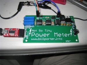
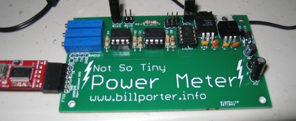
Enter what I call the ‘Not So Tiny Power Meter’. The catchy name comes from the microcontroller I used, ATtiny85, and some sizing issues I had with the enclosure.
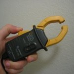
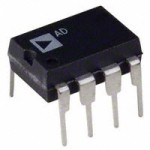
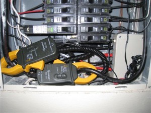
I started out with a plan to use volt-meter current clamps just like the project I linked above (photo of clamp from picobay.com) and use a dedicated chip, the AD736, to convert the AC signal off the clamps to a DC voltage representing the RMS current value. The chips are expensive, tough to use as I found out, and still require external amplifiers to scale up the value to 5V ADC range. So I nixed that idea. Instead, I decided to use a single op-amp to scale up the AC voltage off the clamp and sample it directly with the ATtiny’s ADC. The circuit would be cheap and easy to design and I can convert the signal to RMS in code.
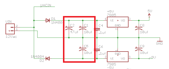
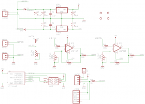
Then I had a thought. If I’m sampling directly, why not measure more than just amps? As an EE, I’d love to know more about my power usage, like power factor, frequency, and a more accurate measure of power by not assuming a voltage like most other projects; but I still wanted to keep the device simple. Then I had another thought: Why not measure voltage through the same transformer that’s giving my circuit power? After a few tests, I found that a properly designed rectifier and regulation circuit wouldn’t distort the source AC waveform too much. They key was to keep the values of the capacitors before the voltage regulator (circled in red) to a minimum, just enough to support a stable DC voltage. Anymore and the inrush when the rectifier diode starts conducting severely distorts the AC wave form.
My design is simple. An AC transformer powers the circuit and a voltage divider drops the source voltage down to ADC range for measuring. A dual sided half-wave rectifier and regulation circuit provides +5V and -5V rails. The AC signals off two AC clamps are scaled up using two op-amps. I planned on using trim potentiometers to calibrate the gains of all the measurement circuitry, but found it was easier to just use transfer functions (found with experimentation) in code. Everything is measured with an ATtiny85, and transmitted out of the breaker panel by a cheap RF transmitter. Since all sources are AC, the ATtiny could only read the positive half of the waveforms. When the signal would go below the ATtiny’s GND, the protection diodes and input resistors would protect the ADC pins from damage. With this design, I can measure voltage & frequency off one phase and current & power factor off both phases.
(Circuit Diagram, Click for Full Size)
The theory of operation is simple. First, the ATtiny85 will repeatedly sample the volts ADC pin for over a full period of the 60Hz sine wave. The peak value of the samples is remembered. Repeat for both current clamp ADC pins. After the max values are captured, the ADC clock is increased for faster sampling, with higher errors. To measure frequency and power factor, I used a 8 bit timer that I extended to 16 bit in software. Using the timer, I measure the difference in time between two peak values of the voltage waveform. Then, I measure the difference in time between a peak value of the volts waveform, and a peak value of the current clamp waveform. Repeat for the second clamp. After all these measurements, some conversions are done to convert the peak values to RMS, times to frequency and power factor, run through a transfer function to account for various gains in the circuit and transmitted out via software serial as ASCII sentences with checksum.
Comparing to real measurement hardware, my project had respectable measurement accuracies of:
- +/- 1 Volt,
- +/- 1 Amp,
- +/- 2% for frequency,
- +/- .03 power factor when current is above 10 amps.
The circuit is designed for 120 Volt, 100 Amp mains, but can be adapted for other systems.
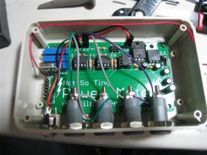
I ran into a few issues through the course of my project. The first issue was with the enclosure. All good projects should be protected by an enclosure, especially when installed into a breaker panel. First my poor planning resulting in a enclosure that was too small to house all the banana jacks for the current clamps. Then the second enclosure didn’t match the mechanical drawings provided by the manufacture. What stinks is I already had PCBs made to the spec of the drawings before I received the case. O well, time for double stick foam to mount the PCB instead inside an overly large box (part of the irony of the name).
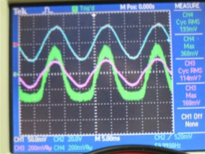
The second issue was the quality of the signal off the current clamps. When using function generators for testing and programming, I could measure frequency, power factor and max value with great accuracy. The noisy signal off the current clamps is another story. Really, power factor measurements with currents less then 8~10 amps are very noisy.
Third, I originally used 434Mhz radios, until I realized it is the same frequency as my external temperature/humidity probe for my clocks. I quickly changed the radios to the lower frequency versions.
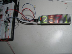
Anyway, I got the project built, tested, and installed into my breaker panel. Everything is internal so nothing extrudes. Right now, the data is received by another one of my projects, an Arduquee display. The display just shows live power usage. I plan to experiment with data loggers to log the data and/or play with the Google PowerMeter API to send the data into the cloud. This project was just to build a sensor to get the data out of my breaker panel.
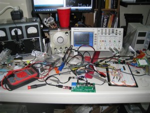
Here’s some photos from the build, and the installation into my breaker panel. Click for larger pics.
Quite a workbench
Checking the signals
Installation into panel
The temporary LED display showing power (Watts), now hanging on my wall. Notice the RF receiver on the left.
My design is open-source. All the theory of operation is well documented in my code, and all code and Eagle PCB files are available to download:
Not So Tiny Power Meter files(zip)
I even have extra PCBs for any that what them, $5 plus shipping. Drop me a line in the comments if interested.

This work is licensed under a Creative Commons Attribution-ShareAlike 3.0 Unported License.

