
DIY Museum Exhibit – Reaction Time Challenge
Posted in Education Outreach, Museums, Projects by Bill
24 Aug 2013

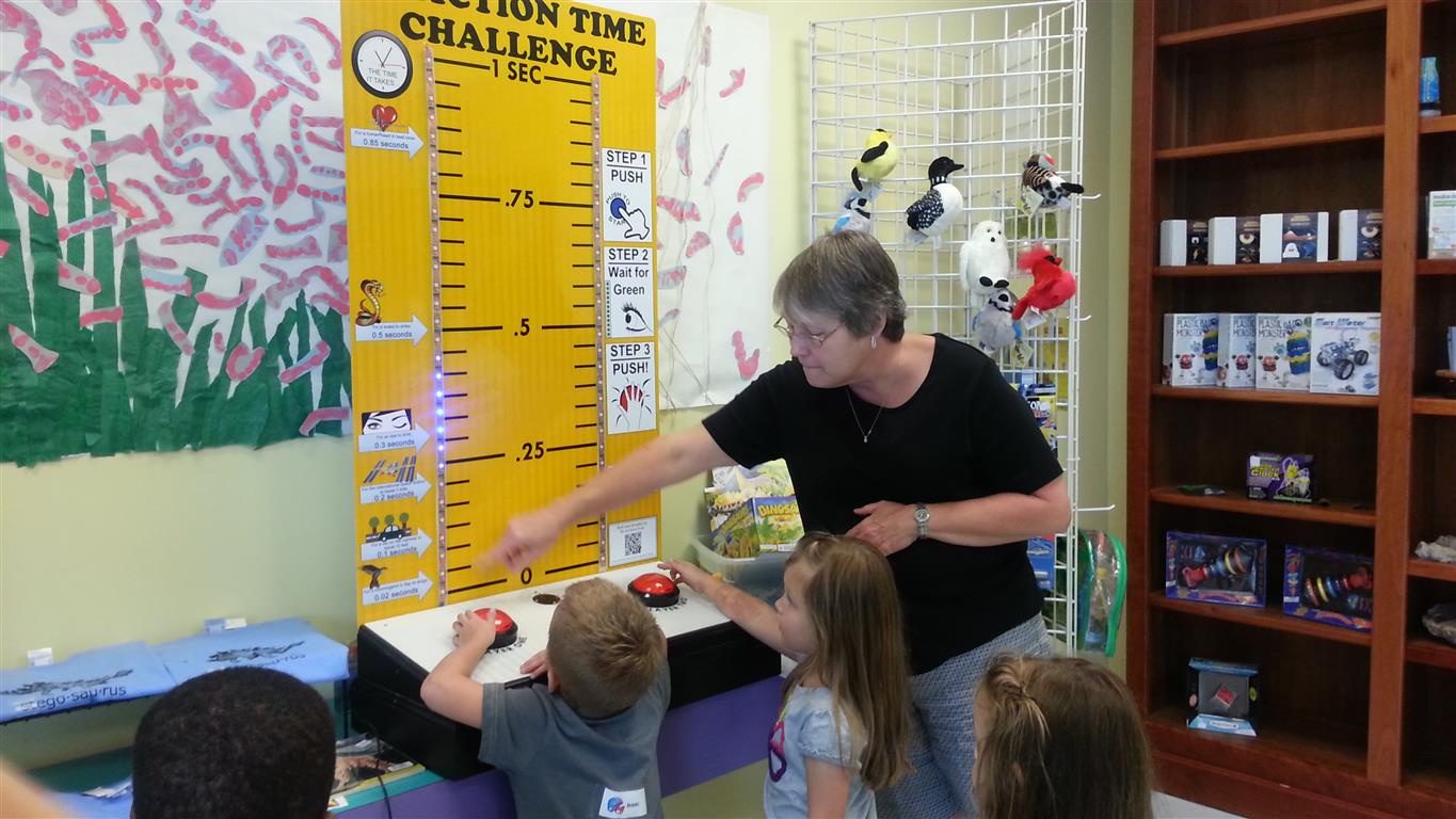
Ok, so I have a thing for local Science Museums. What are you gonna do about it? Me, I built an exhibit from scratch and donated it to the Science and Discovery Center of Northwest Florida. This exhibit is a simple game that pits two people against each other to find out who’s got the faster reaction time; and learn some things on the way! Powered by an Arduino, the electronics and construction are so basic I’m posting everything on GitHub and here for others to clone or improve upon. I bet there’s a local science museum near you that would love an exhibit like this. *wink*wink*
Theory of Operation
The operation is simple. When no one is playing the game, pretty colors patterns (provided by Adafruit) cycle across the LEDs on the back board and a backlit ‘Start’ button blinks away asking to be pressed. When a game starts, yellow bars will blink a few times before turning green, prompting the players to smash the large red buttons as fast as possible. The number of times the strips flashed yellow and then the final delay before turning green are both random, making it impossible to ‘cheat’ the game by predicting the upcoming green flash. The time it took each player to react is displayed by the LED strips like a ruler. This lets the players visualize their reaction times and compare it to some other interesting times. If a player hits a button early (or tries to cheat and fails) the strips flash red and the game ends early.
Construction
I’ll start with the mechanical construction because, well, I didn’t build it! The disadvantage of living in a 700 sq-ft apartment means I don’t have the required tools for carpentry like this. Thankfully, I have a coworker with a husband that is great at building things. A quick lunch meetup and a poor drawing on a napkin later, he had enough information to build this beautiful exhibit. He has access to the same sheet metal that roadway signs are cut out of and the cutter that does the… cutting. So he made most of the display with that metal and built a box out of particle board for the lower cabinet. (Pictures are click to enlarge)
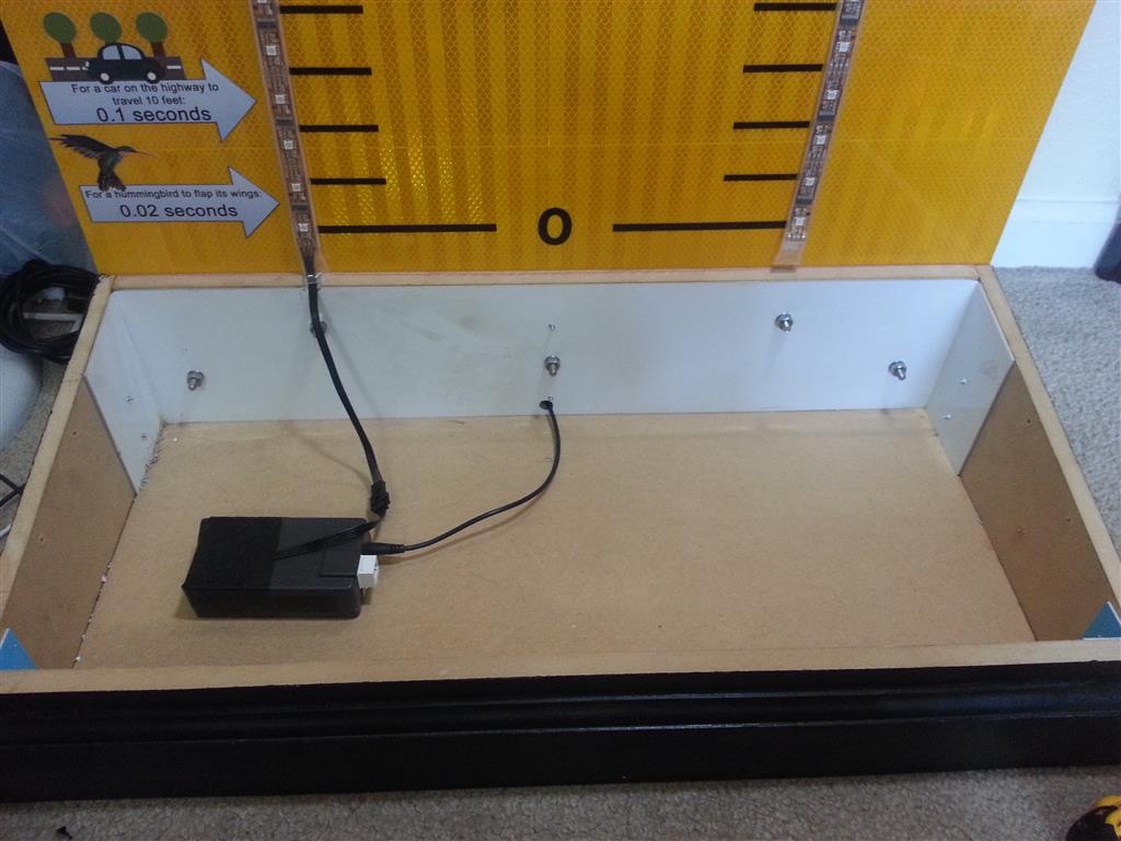
Lower cabinet

Side view
You can see he reinforced the backboard with wood that is bolted to the lower cabinet.
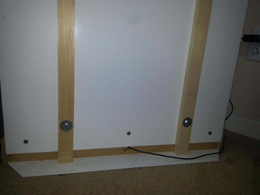
Lower back
The rough dimensions of the display are 4′ tall by 2.5′ wide. The lower cabinet is about 8″ tall and has about a 20 deg slant. If you build an exhibit like this exact dimensions are not that important.
Electronics
Ok, now onto the part I know all to well, the electronics. The buttons come from 2 sources, Sparkfun and Adafruit. I used the ‘Big Red Button of Doom‘ on Freeze Frame, and had two more left over. The LED backlit start button was a spare from another museum project (not yet posted). Both cases the LEDs already in the buttons were no good to me. They expected 12V or were just to dim, so in all three cases I took the buttons apart and replaced the internal LED and resistors with my own parts.
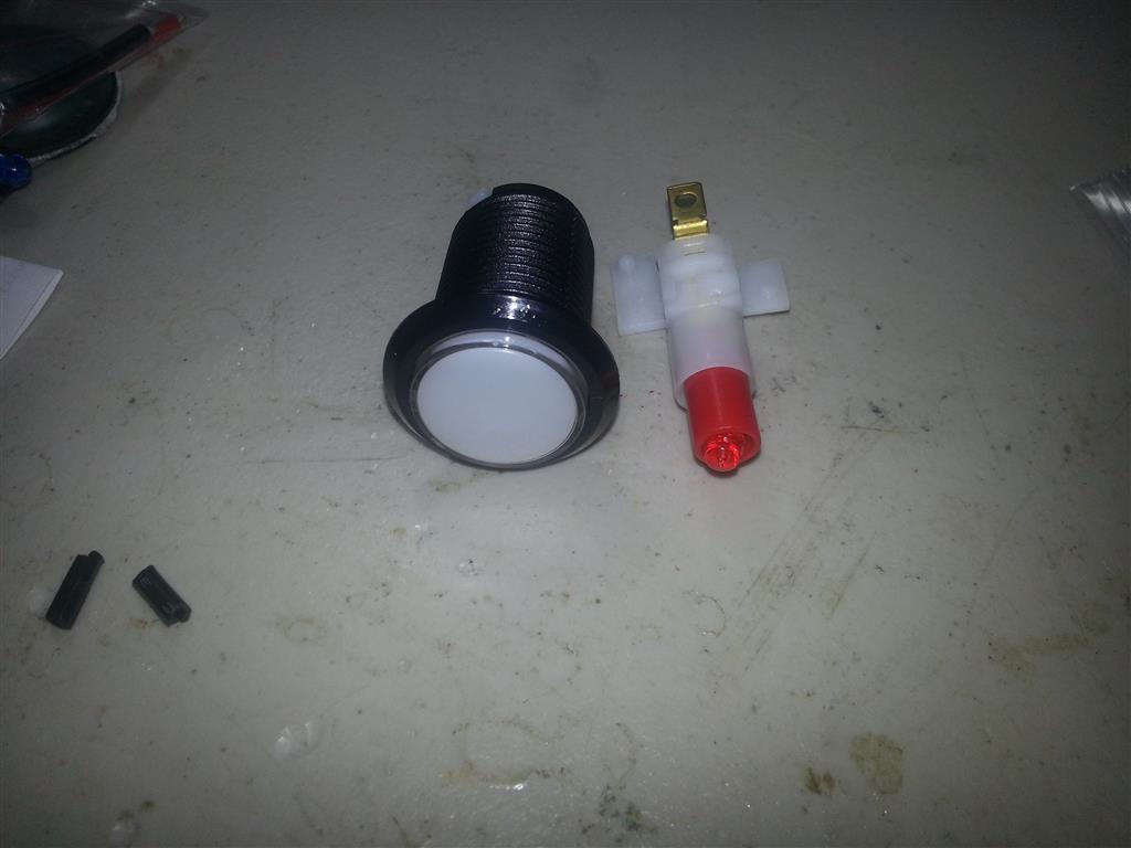
Button and LED module
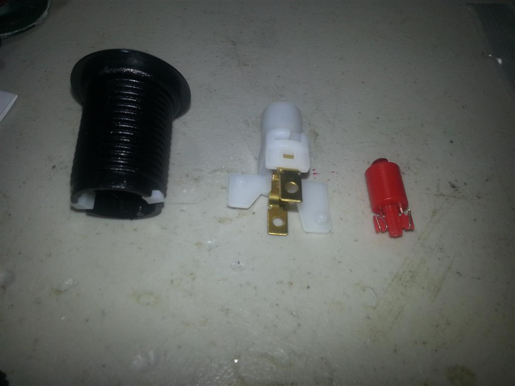
Remove the LED module

Bend pins back
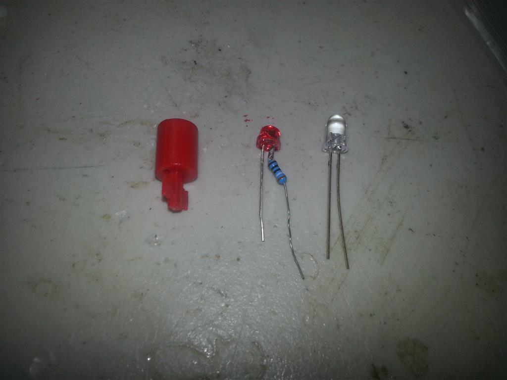
And remove LED
I picked out some high-brightness LEDs and the correct resistors for 5V operation. Soldered them together just like the original was configured (NOT SHOWN) and installed them into the buttons just like the originals.
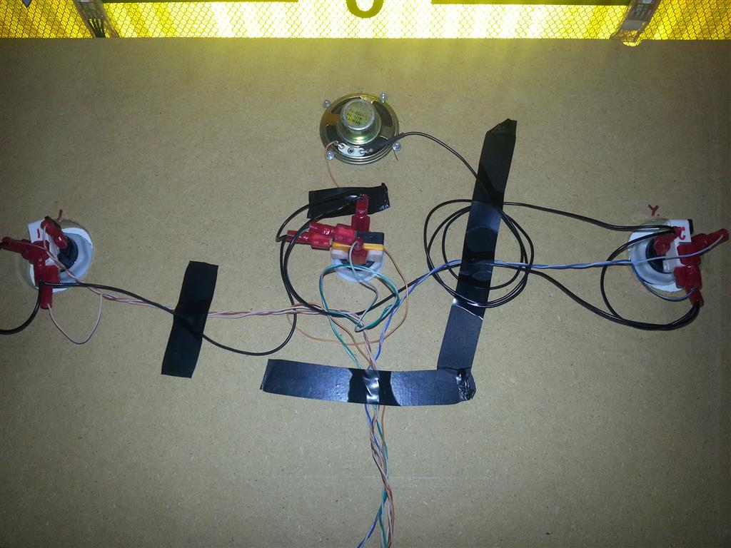
The speaker is a regular 8 ohm speaker and only needed a 100 ohm resistor wired in series.
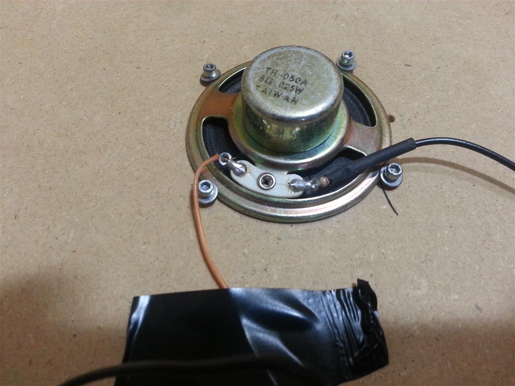
Resistor in series with the speaker
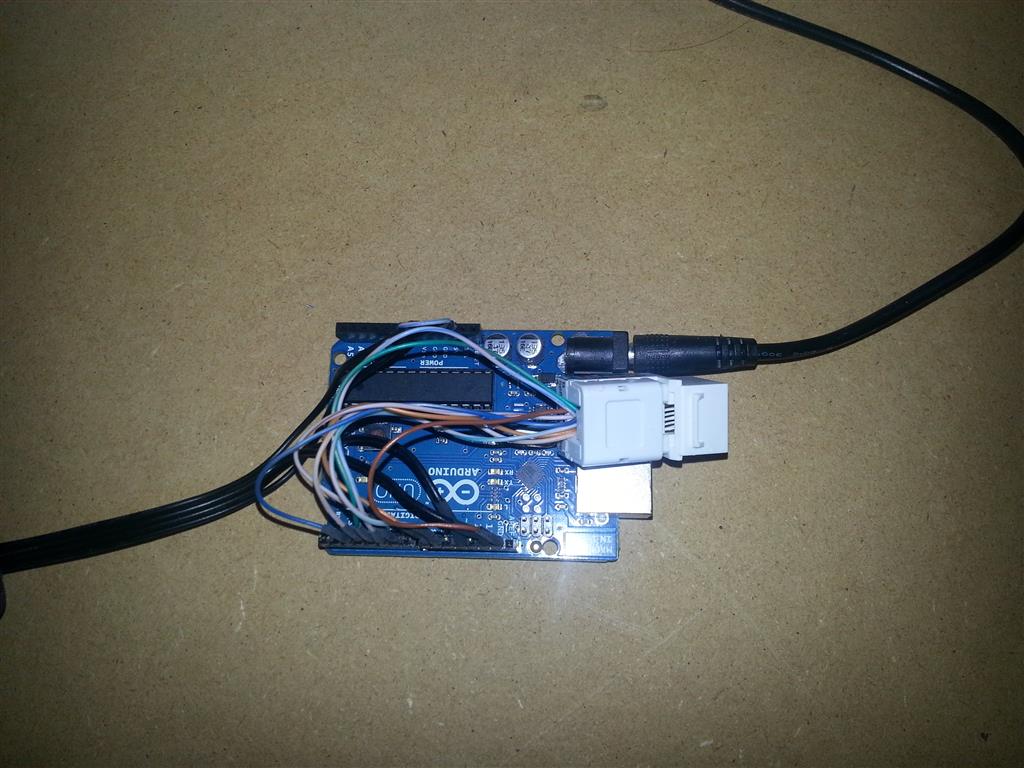
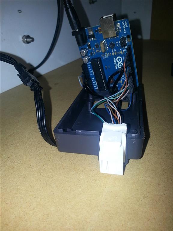
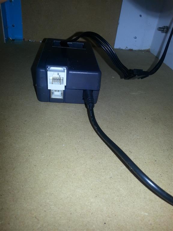
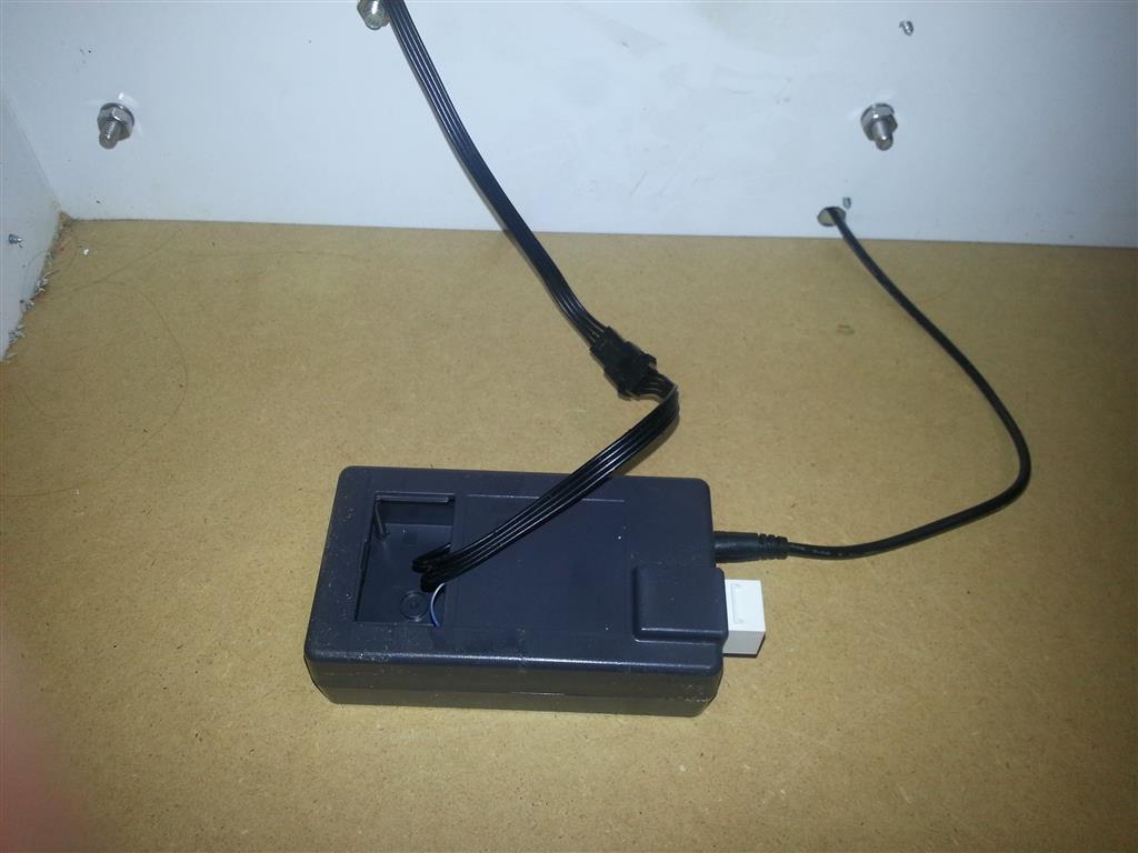
The brain is a vanilla Arduino board in an Arduino project enclosure. No bells or whistles in the form of a shield. Since the Arduino project enclosure was designed to house an Ethernet shield, an Ethernet jack fit nicely in the hole in the top cover and I decided to use that to make all the connections with components. I cut a Ethernet cable in half and pealed back most of the jacket exposing a good length of wires. I ran those wires to the three buttons with LEDs using spade connectors and to the speaker. Everything shares a common ground, meaning I had to use all 8 wires on the cable. I used extra pieces of the Ethernet cable; crimped them to the Ethernet jack and soldered the other ends to pinheaders to mate with the Arduino.

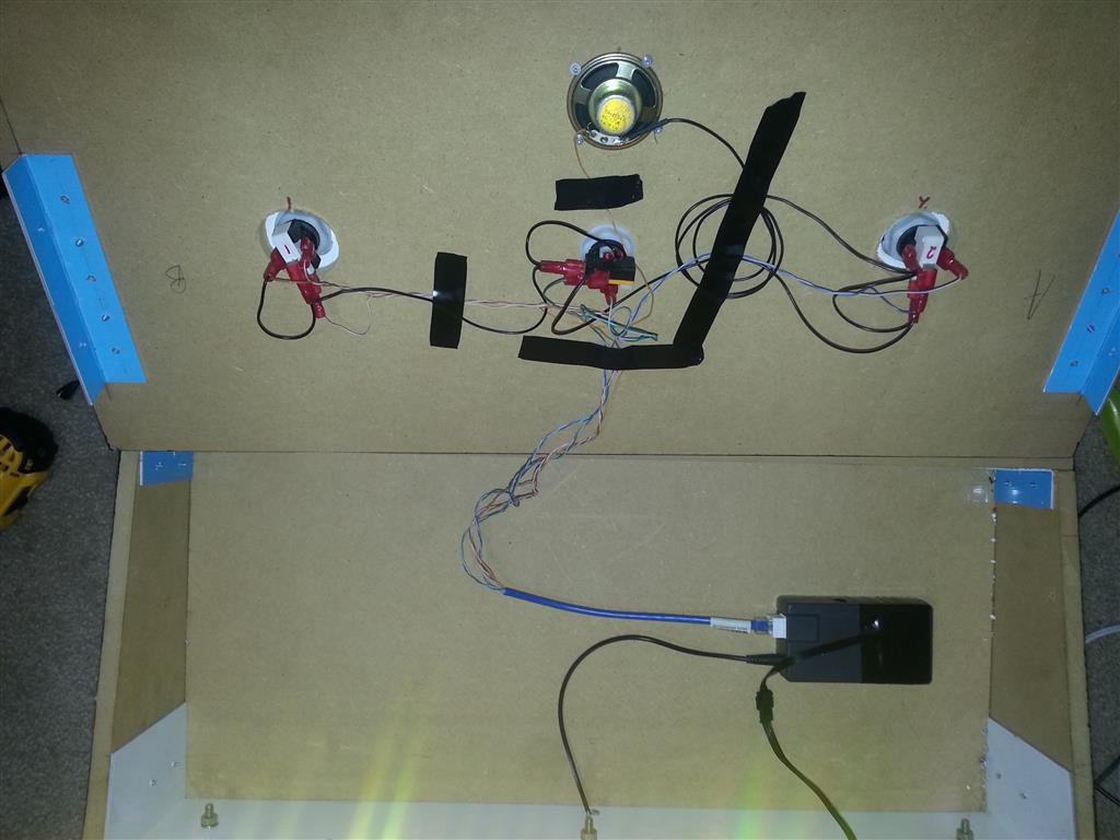
The weatherproof LED strips came from Adafruit and included connectors that I also soldered to the pin headers and ran through an opening on the other end of the enclosure. I used 3M double sided tape to secure the LED strips to the backboard. These controllable strips have an ‘IN’ and ‘OUT’ side to them. I started with the left strip and faced the ‘IN’ side down. I ran the left strip from bottom to top and then used a 4 wire ribbon cable to jump the electrical out of the ‘OUT’ side on the left strip and into the ‘IN’ side of the right strip, which I started from the top this time. I ran the wire behind the backboard.

LED strip wiring

Connections between strips behind backboard
This is the complete wiring diagram.
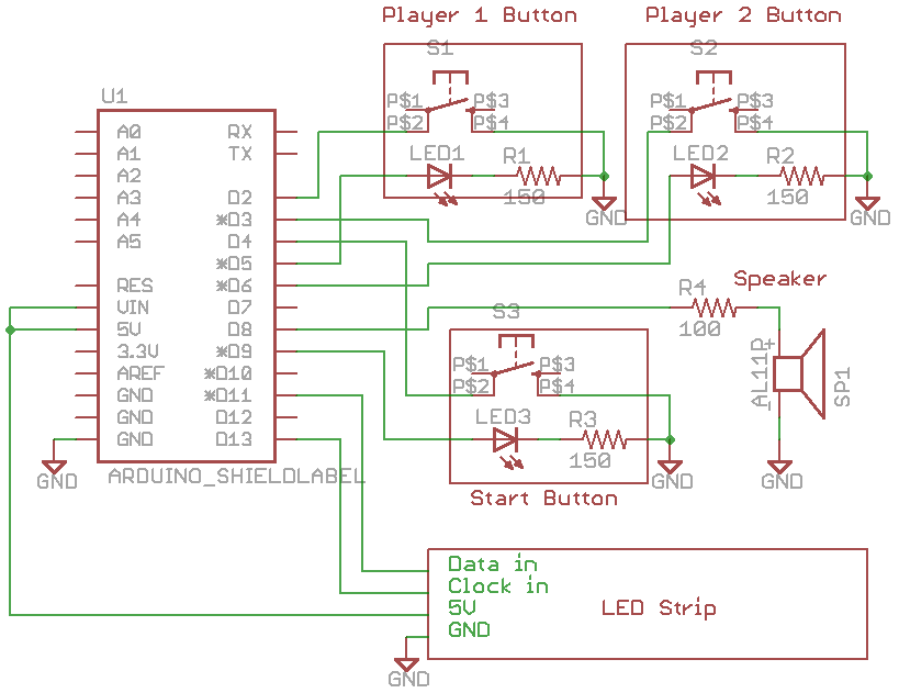
Wiring Diagram
Notice I jumpered VIN and 5V. The voltage regulator on the Arduino won’t handle running the LED strips. So I bypassed the on-board regulator with this jumper and used a switchmode 5V power supply to give everything the voltage it needed.
Decals and Science O my!
My coworker’s husband cut the vinyl labels for the ‘time ruler’ and the name. Though now that we own a Silhouette Cameo we could easily do that ourselves. My wife and I came up with a few interesting time events to add to the ruler by comparison. She also created the exhibit directions running down the right side.
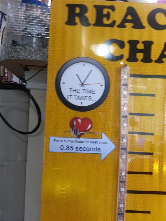
The time it takes…
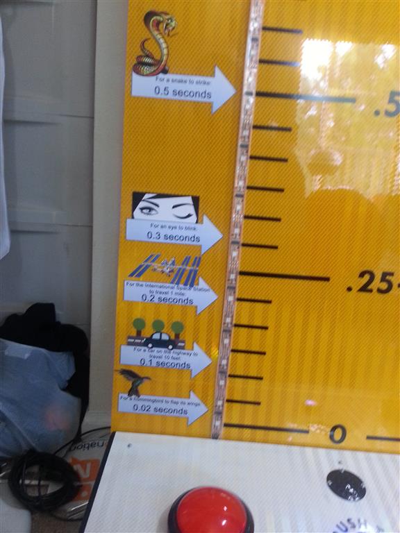
Sorry about the quality
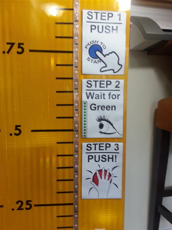
Directions
We also added a suggestion to play by audio only to see if that affect reaction time, and a nameplate with a QR code that points to this post.
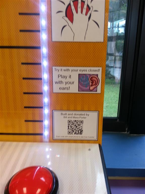
All these graphics and the Photoshop source files are included with the code on my GitHub.
Time to Build one for your Museum
So you want to build one to? I’ve included everything I can to help you on your way. You’ll need some basic soldering skills, a few parts from a hardware/electronics store and the parts I list below.
Alright, like I covered above you are on your own for the backboard and cabinet construction. Since I didn’t build this one I don’t have many details. But most museums have a handyman volunteer that could easily tackle this build.
Electronics I can help you out on. If you haven’t already noticed, my two favorite sources for parts are Sparkfun and Adafruit. I’ll post links for parts from both sources and give an average price. Total cost of the electronics comes in right around $150.
- Arduino SFE ADA $30
- *Arduino Enclosure SFE ADA $12
- Power Supply Digikey $19
- Red Buttons (need 2) SFE ADA $10
- **LED Start Button SFE ADA $4
- Speaker SFE ADA $2
- ***LED Strips (need 2 meters) SFE ADA $30
- ****Red LEDs (need 2) SFE ADA $1
- ****Blue LED SFE ADA $1
- ****150 Ohm Resistors (need 3)
- ****100 Ohm Resistor
* Only Sparkfun carries the box I used
**Only Adafruit carries the LED button I used for start, but I linked a non-backlit SFE as well
*** I used Adafruit strips for their lower price. Sparkfun caries something that would work but would require code changes.
****Adafruit does not sell the LEDs individually. Resistors can be bought at a local Radio Shack or equivalent.
You’ll need a handful of other things, like an Ethernet cable, jack, shrink tubing/electrical tape, etc if you want to copy I how I wired it together. All these things can be had at a local Radio Shack or equivalent.
If you have any questions, use the comments below.
Download all source files Here
This work is licensed under the Creative Commons Attribution-ShareAlike 3.0 Unported License. To view a copy of this license, visit http://creativecommons.org/licenses/by-sa/3.0/ or send a letter to Creative Commons, 444 Castro Street, Suite 900, Mountain View, California, 94041, USA.

Trackbacks / Pingbacks