Our Geeky Wedding – Electronic Wedding Wishing Well (eWWW)
Posted in Projects, Wedding by Bill
8 Oct 2012

This is the first (and probably only one before the big day) post regarding my upcoming geeky wedding. This was one of those last minute “How can we make this our own?” efforts we wanted done in time for our engagement party. Mara had bought a cheap cardboard ‘Wishing Well’ for the party and our wedding. It was cute, but bland and uniform. We wanted to make it into something original and something that matched our theme ‘Circuits and Swirls’. So we turned it into the ‘Electronic Wedding Wishing Well’.
The base well comes from Oriental Trading for a measly $11. It was cheap and not very sturdy but got the job done. We ended up reinforcing the top with cardboard and covering up the electronics and wires with more cardboard.

Original Well
I had an idea in my head about I wanted it to do but I was short on time and money. In my case, I had less time then I had money, so I put together a shopping list of breakout boards that would get the job done.
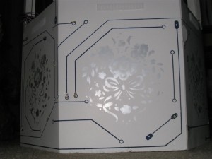
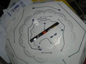
In the mean time Mara set out to pant the well in the same styling (Circuits and Swirls) as our wedding theme. You can see that styling in the banner above. The base pattern on the well satisfied the swirls aspect, but it needed some circuit traces. She masked lines on the sides with electrical tape and painted the traces. After they dried she hand pained the pads on the end of each trace. (Click pictures to enlarge)
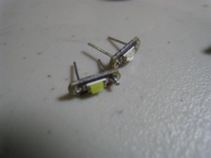
Then it was time for the upgrades. We first took a handful of LillyPad Micro LEDs and soldered leads to them.
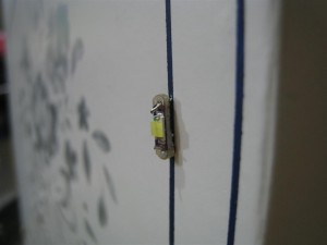
This allowed us to attach the LEDs to the side walls by poking them through the cardboard and bending them back.
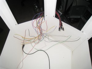
I then soldered hookup wires terminated with headers to groups of 2 LEDs connected in series.
We also added two RGB LEDs to the top of wishing well base that light up the tissue paper roof to the well. We also reinforced the top cover with a layer of thick cardboard.
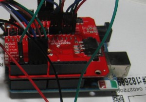
The brains behind the show is a run of the mill Arduino mated with a PWM Shield for running all the LEDs.
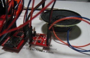
To play sounds along with the show, I settled on this Audio Playback breakout. It seemed to be the cheapest, but easy to implement solution out there. I also threw in a cheap speaker amp as well just to make sure it was loud enough.
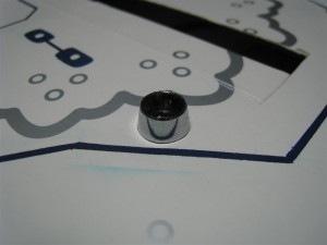
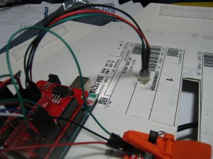
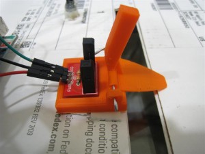
To trigger the show, I designed and 3D printed a latch that would trip a photo interrupter.
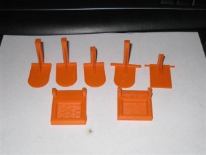
It took a few tries to get it to work right.
The 3D files for the trigger mechanism are on Thingiverse.
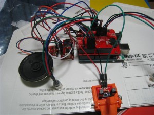
Here’s a picture of all the electronics mounted on the top of the well.
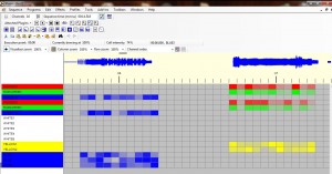
With the hardware in place, it was time to program the show. I created an MP3 of the sound effects I wanted to play, but didn’t have an easy means to program a light show to match. I considered doing it by hand. After all a light show choreographed to music is just a list of brightness values played back at a steady rate with the music. Trying to do that by hand though seemed like a daunting task without a quick way to make adjustments.
So instead I started looking at the same programs used to make those impressive Christmas light shows. The popular one, Light-o-Rama sadly isn’t free. I looked around for a while and found a clone that is free called Vixen.
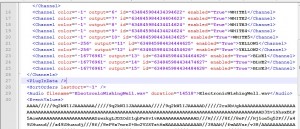
Even better, it saves sequences as plain text XML! Perfect for extracting data. Well, almost perfect. While the XML is plain text, the actual data that makes up the light sequence is stored as a binary list of numbers encoded to base64 ASCII. Further more it had no identifiers for channel or frame number so the data has to be parsed carefully to extract the right order of frames in channels.
Hmm…
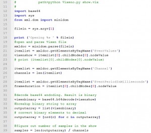
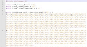
Well, hey an excuse to learn some more Python! I’m barely to the skill level of being able to hack python scripts so I spent a few hours Googling and learning. After that I had a script that would parse Vixen Sequence files and output a array formatted for Arduino of all the data that makes up the light sequence. (I have since wrote a Tutorial on the process to help anyone else wanting to do something similar.)
Now I could use Vixen to design the light show with the music and easily embed the show onto my Arduino. With gratuitous program space (32k) I figured I didn’t need any external storage for the light show file. I’d simple store it in program space on the Arduino. My 14 second show of 16 channels and 20 frames per second only took up 4k of space. Room to spare. The python script formats the array to be store in program space.
To playback the show, it’s a simple function to code.
void playShow(){

  //start music track
  wtv020sd16p.asyncPlayVoice(0);
  delay(100);

  int temp = 0;
  long start = 0;

  //start playing back show file and run LEDS
  for(int i = 0; i<vixen_frames; i++){
    start = millis();
    for(int y = 0; y<vixen_channels; y++){
      temp = pgm_read_byte(&(vixen_show_data[y][i]));
      temp = map(temp,0,255,0,2048); //scale to lower half of TLC range.
      Tlc.set(y, temp);
    }
    Tlc.update();
    delay(vixen_frameduration - (millis() - start));
  }

}
The idea is simple, load up 16 channels of values for one frame, update the TLC chip, and then wait for a bit and do it again for the next frame. You might notice it’s a bit trickier to pull values from program space. You have to use the pgm_read_byte() macro with the address to the array in memory. If you don’t you get random data.
After uploading the firmware, The EWWW is complete. The parts list (without the Arduino) comes to about $92 but I had some of the needed parts lying around.
Video
Source Code
The source for what’s running on the Arduino is available HERE.
For the python script and a tutorial on using it go HERE.


Trackbacks / Pingbacks