
 This is a build guide for ESPixel GECE a WiFi pixel controller for General Electric Color Effects (GECE) pixels. This also includes iTwinkle by GE. Based off the ESP8266 chipset, this design will replace the original controller on the strand and turn the string into a full fledged e1.31 sACN device. The firmware includes a web server that allows the end user to adjust the various settings. This guide will take you through assembly with the assumption you know how to solder parts to a circuit board.
You can download the source files for the PCB with parts list here and the firmware is available here.
Building
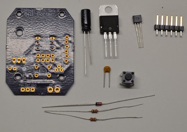
Let’s start by making sure we have all the parts ready.
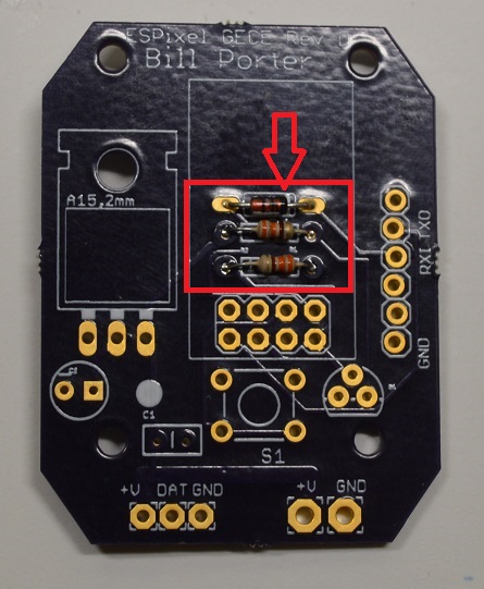
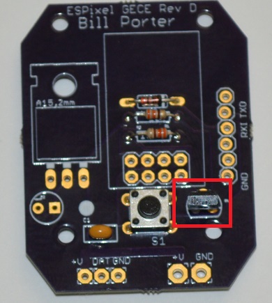
Next we will add the diode and the 2 resistors. Note the direction of the black line on the diode! It must match the white line printed on the circuit board. It does not matter which way the resistor goes.
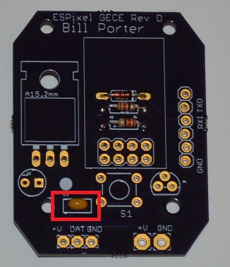
Then the 0.1uF capacitor. It does not matter which way it goes.
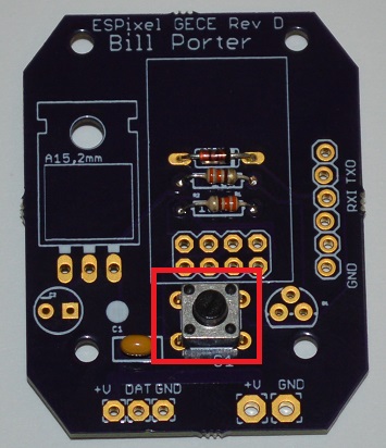
Next is the push button. The push button can fit on the board one of two ways. Either way is fine.
Then it’s the MOSFET. Look closely at the FET. You will notice it has a semi-circle shape with one flat side. Look closely at the PCB. Notice it has drawn the same shape. Make sure when you install the FET it matches the PCB.
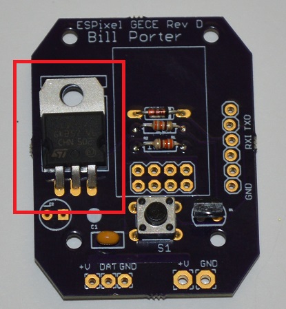
Next is the Voltage Regulator. You will have to carefully bend the pins so after it’s inserted, it lies flat back against the PCB with the metal tab on the bottom.
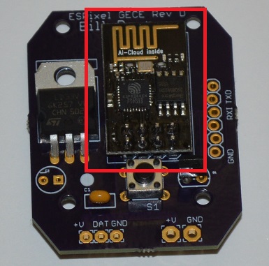
Now it’s time for the big part. We are going to solder the ESP chip directly to the carrier board. Fit it into the PCB and try your best to keep it level. Pay attention to how much heat you use on the pins, as if too much is used, it may melt the solder holding the pins to the ESP board.
Then solder on the 6 pin connector making sure it ends up flat against the PCB.
Next is the polarized capacitor. It DOES matter which way this one goes in. On the PCB, there is a small minus (-) sign above one hole. On the capacitor, the pin on the side that has a white strip painted on it needs to go though this hole.
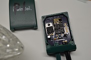
The board is built, so now it’s time to replace the factory board in the GECE blob. Start be taking the original blob apart. I used a small flat head screwdriver, as I don’t have triangle bits. You may have to give it a few whacks with a hammer to get the plastic fill to give up it’s hold on both pieces of the enclosure.
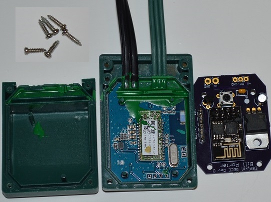
Next remove the orginal PCB as best you can without damaging the plastic enclosure. A hammer may be needed again. When it’s out, flip the board over to expose the electrical connections. Use a multi-meter to verify, but the electrical connections should be as shown:
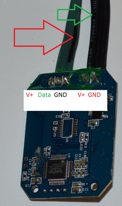
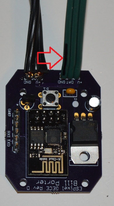
I marked the GND wire on the pixel string and note the V+ wire on the power supply had the text.
With wires marked, cut them off the original PCB, strip them and solder them to the new PCB.
The kit is built, and now it’s time to program it.
Uploading the Firmware
Now that you have built the adapter, time to upload the code. We will be using the Arduino IDE (v1.6.5, available HERE) to upload the code. Follow the instructions HERE to add support for the ESP8266. Select ‘Generic ESP8266 Module’ as the board type.
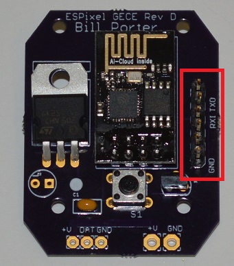
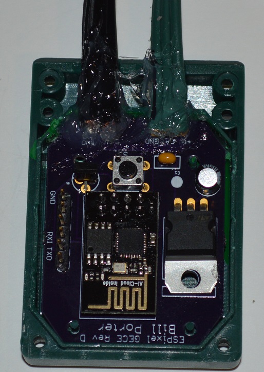
Connect the programming cable to the ESPixel PCB, paying attention to the TX, RX and GND locations. Every programmer may be different.
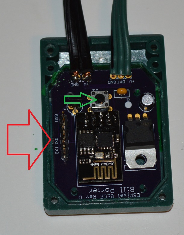
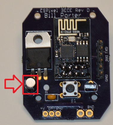
You will need to power the entire pixel string and controller during programming. If you are using the orginal power supply, that is fine. Just make sure to hold down the PROG button (shown above with the green arrow) as you plug in or power on the GECE string.
Download the firmware from HERE by selecting ‘Download Zip’ on that page. Unzip the folder from the zip file, rename it to ‘ESPixelStick’ (remove the -master) and open up ‘ESPixelStick.ino’ in Arduino. Hit upload and wait for the magic to complete. After that, it’s best to power cycle the ESPixel once so it gets to a good state, then you should be ready to configure controller settings.
Configure
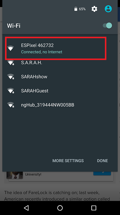
When you first power up the Reanrd with new WiFi adapter, it will broadcast a WiFi access point with an SSID of “ESPixel xxxxxxxx” where the x’s are a serial number specific to each WiFi chip. Using a smartphone or other device, connect to that wireless network.
Then bring up a browser and navigate to 192.168.4.1
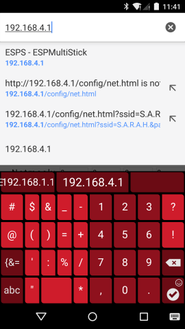
And you should be greeted with the config page.
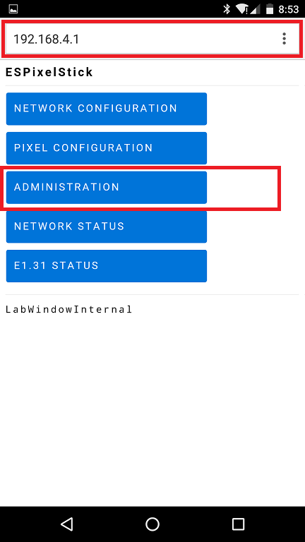
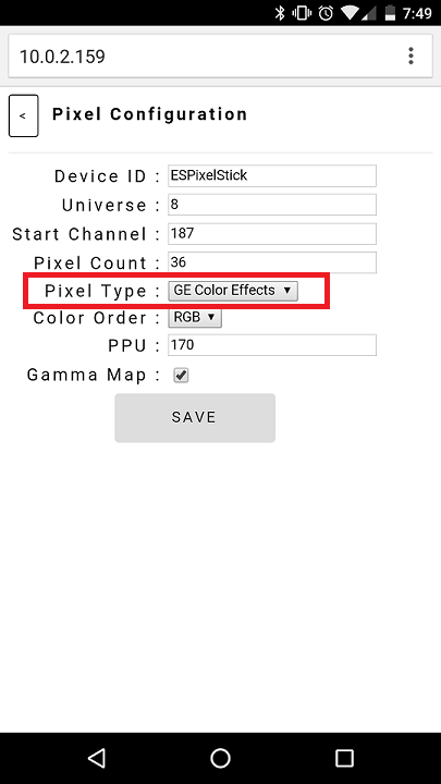
Go to Pixel Configuration (ignore the red text box in the above photo) and change pixel type to ‘GE Color Effects’ and save:
Next return to the main page and navigate to the “Network Configuration” page. Here we will set the WiFi adapter to join your existing show network and give it a new static IP. Use the list at the bottom to fill in SSID be clicking on your network and enter in a password if required. Clear the checkmark for DHCP and change the static IP address to match your network setup. If you plan to send the e1.31 sACN data via Multicast instead of Unicast, make sure to check that box.
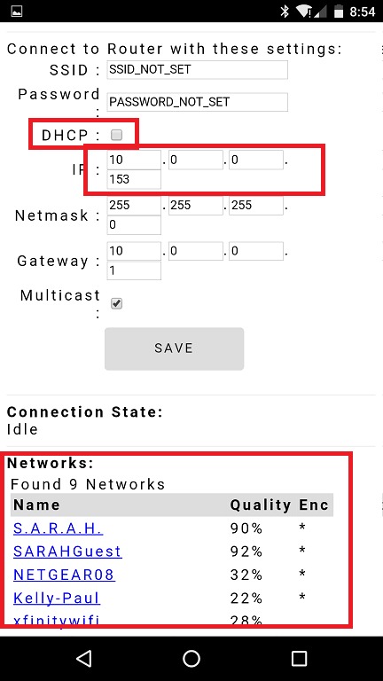
Hit ‘Save’ and the WiFi adapter will reboot and apply the settings. The “ESPixel xxxxx” WiFi network will be gone as it will now have joined your show WiFi network you configured above. Connect to your show WiFi network with you phone or laptop and using a browser bring up the config page again using the static IP address you just assigned to the adapter. In my case, the new address would be 10.0.0.153
Sealing Back Up
Before I closed up the enclosure, I used some silicone RTV to try and keep the wire connections as waterproof as possible. I suggest doing the same for your strings.
Troubleshooting
If you have an issue with WiFi adapter and need to reset the configuration, there’s an app for that! No not really, but you can force the ESPixel adapter back into AP mode. Simply turn off your wireless AP and then power up your GECE string. After a 20 second timeout, the adapter will go back into AP mode.
If you need to upload new firmware depress the button on the adapter and connect the string to power. You can then use the Arduino IDE with the ESP8266 core to upload new firmware.

Trackbacks / Pingbacks