
Our Geeky Wedding – DIY Electronic Wedding Invitations (DEWI)
Posted in Projects, Wedding by Bill
29 Jan 2013
")
Next up in the progress towards our ultimate geek wedding are the wedding invitations! Not content with plain old paper invitations my fiancée Mara and I smashed our geeky heads together to come up with a design that keeps with our circuits and swirls theme. We decided to be more literal, by putting actual circuits into our invitations! However, time spent on design, production and cost were a concern. We had to make about 50 invitations to be sent out to our guests.
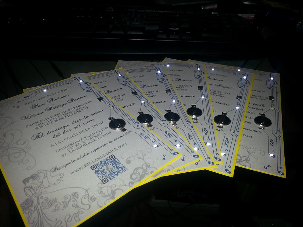
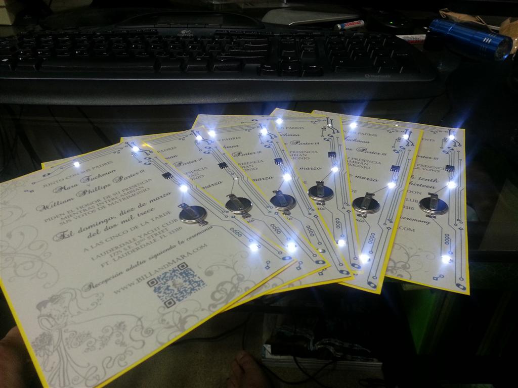
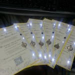
First I’ll jump right to the end product. What follows is a video of our invitation and a few photos taken during development and production. If you notice something odd about the light show in the video, jump to the end of the post for an explanation.

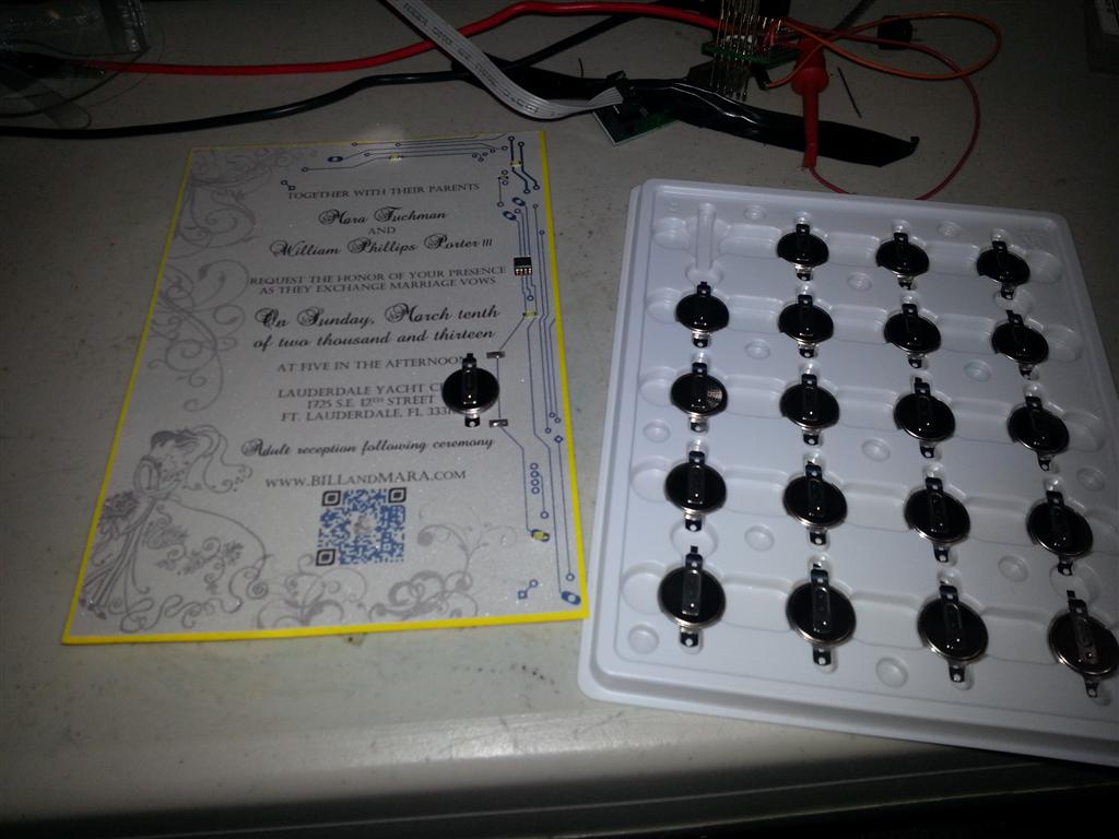
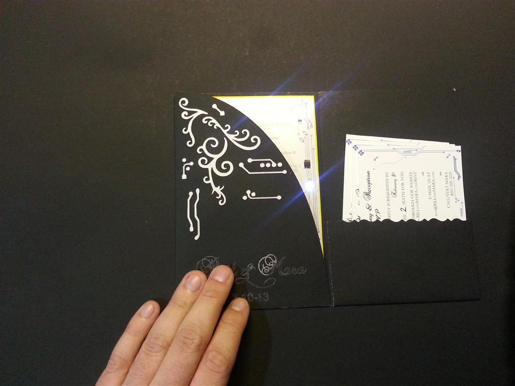
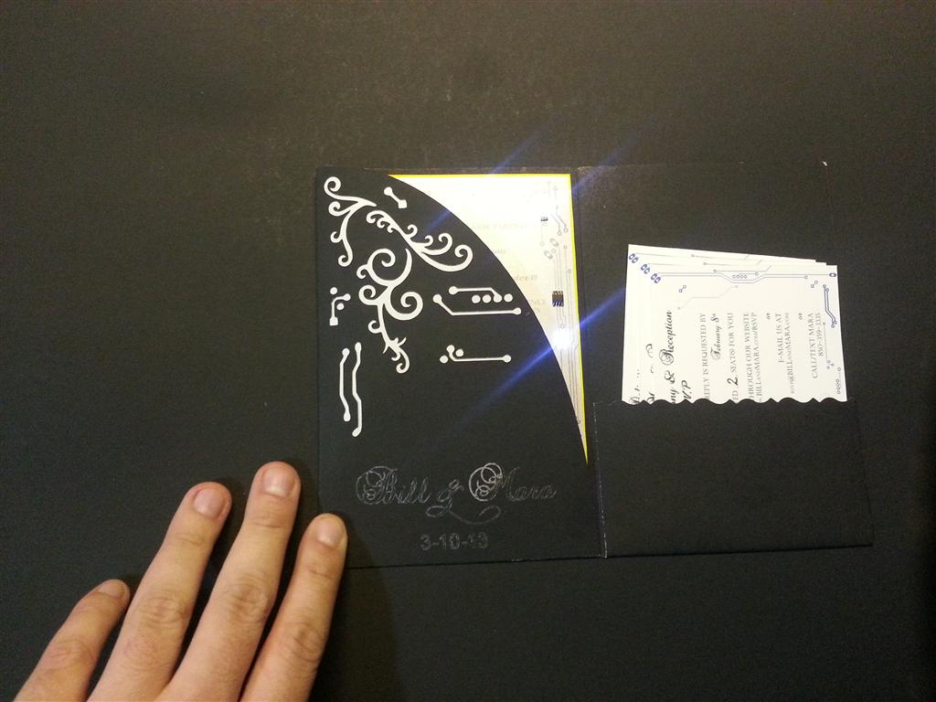
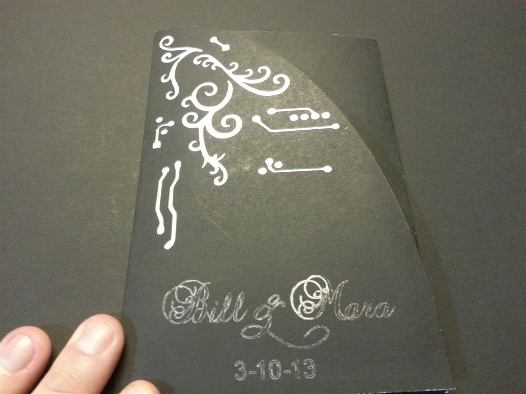
Front cover

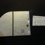
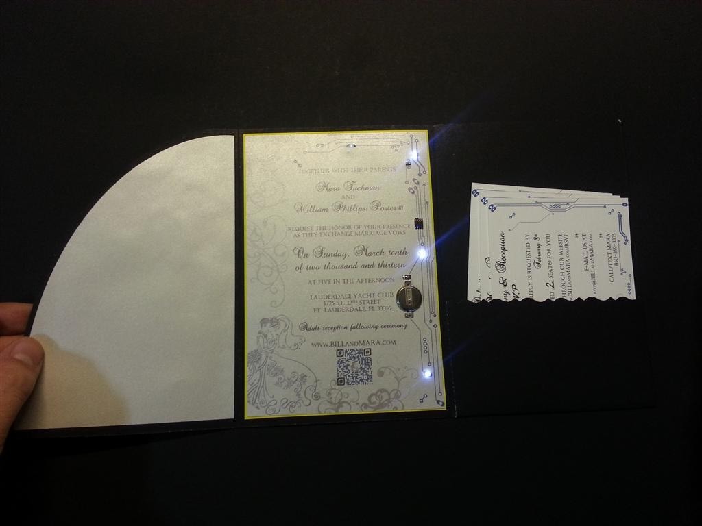
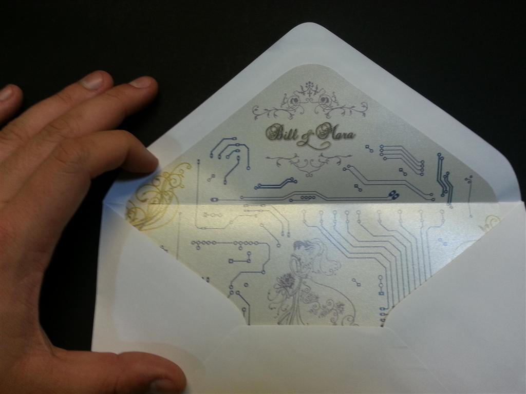
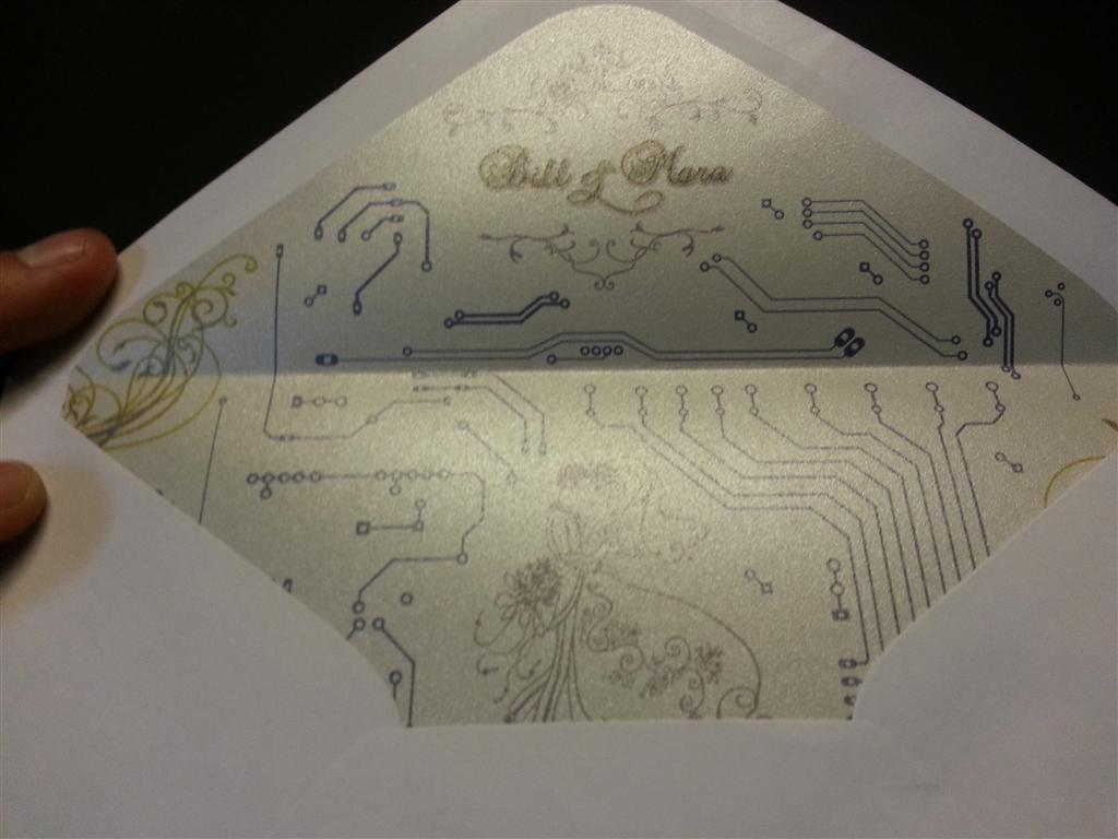
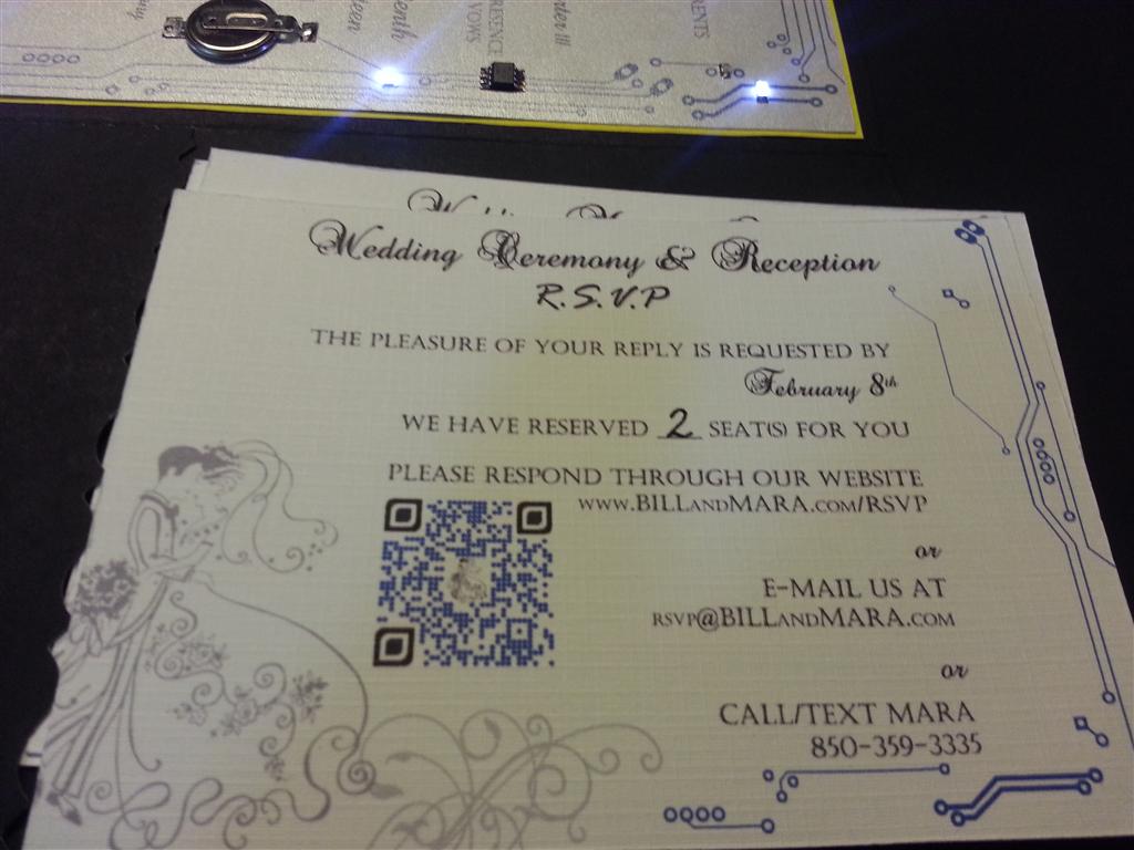
Inside finished card
The Design
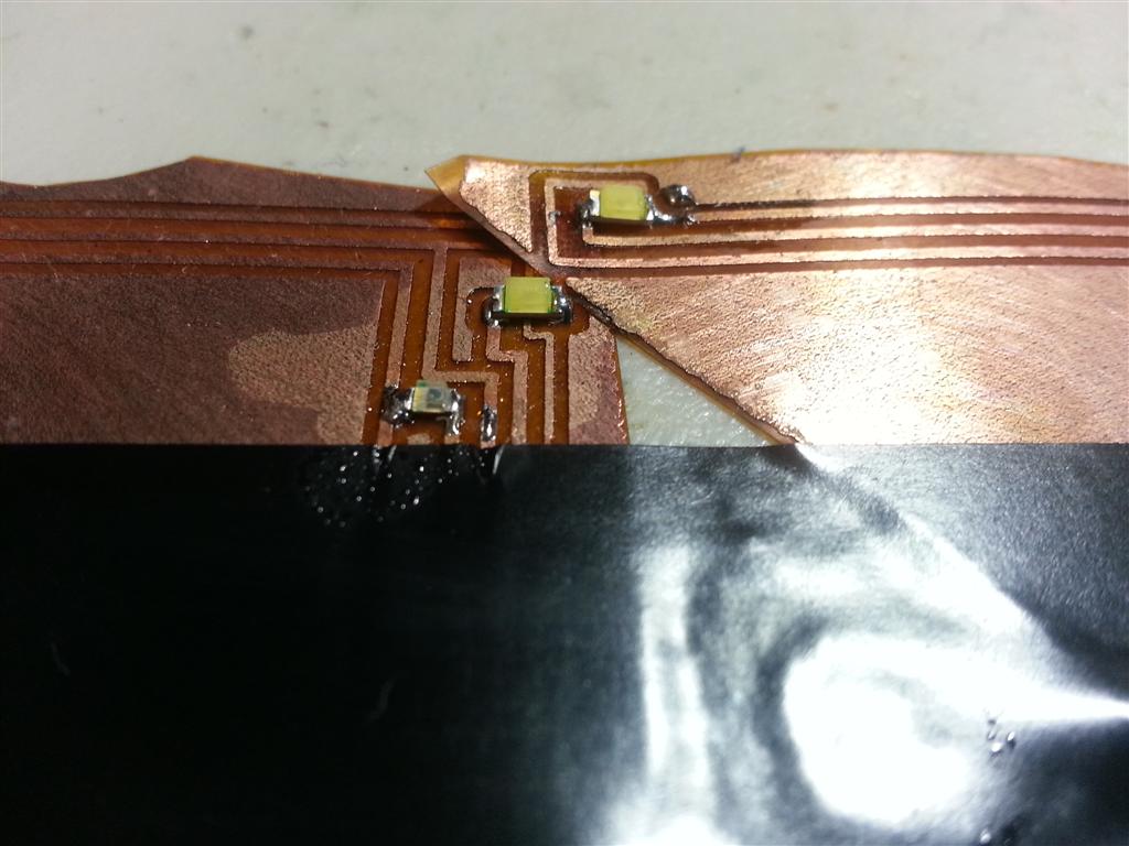
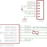
With time and money acting as constraints I kept the design quite simple. The theme of our wedding is ‘Circuits and Swirls’ and Mara was already ahead of me on the invite design. Two sides of the cards had stylish circuit traces running up and down while the opposing sides had swirls. I figured it would be neat if the stylish traces actually terminated to real working parts, in this case twinkling LEDs; something simple to implement while cool. I pulled up Digikey and priced out the cheapest white LEDs, AVR MCU, battery and light sensor (if you are thinking I could have used one of the LEDs as a light sensor, see Lessons Learned). The light sensor consists of a phototransistor biased by the internal pullup resistor in the AVR. Running at a system voltage of 3V also meant resistors in line with the LEDs were not needed, the IO pins would keep more than 20-30 mA flowing out even if the LEDs tried to draw that much.
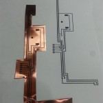
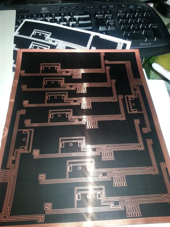
I crafted the circuit and Eagle and then started the board layout when I ran into my first obstacle. The card design was larger than the allowable work area in the free version of Eagle. Well, since I was going to be panelizing and ‘printing’ these boards, I had an idea. I laid the design out in the confined space in Eagle, then exported the design as an image. I took that image into Photoshop and extended two of the ends into the final positions. I also used Photoshop to panelize the design onto 8.5″x11″ sheets. I was able to fit 9 designs on one sheet.

Simple design

Board layout before Photoshop stretching

Early revision

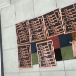
Panelized design

How many do I have to make again?
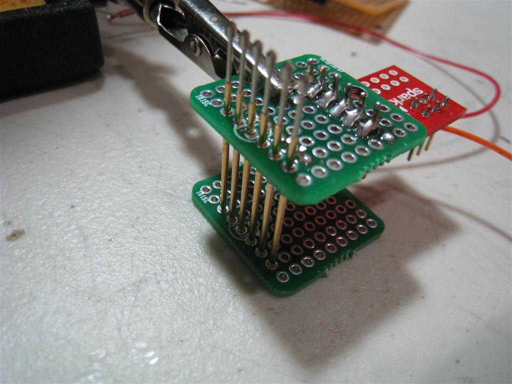
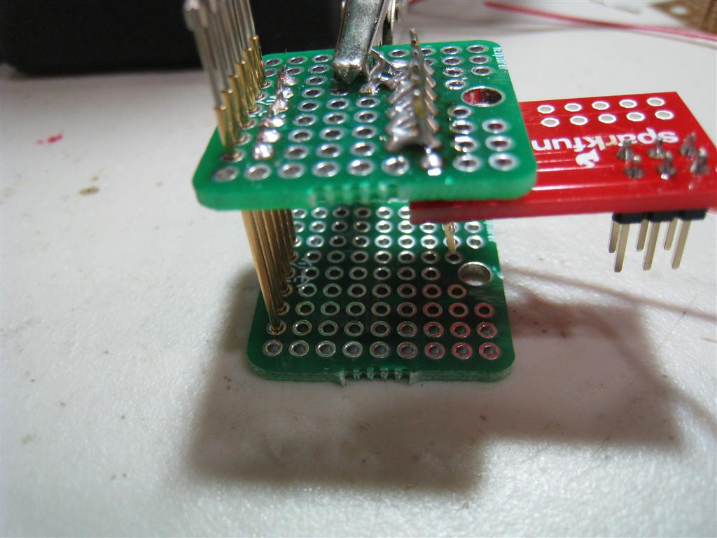
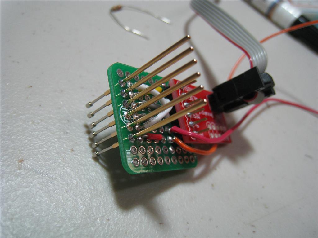
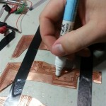
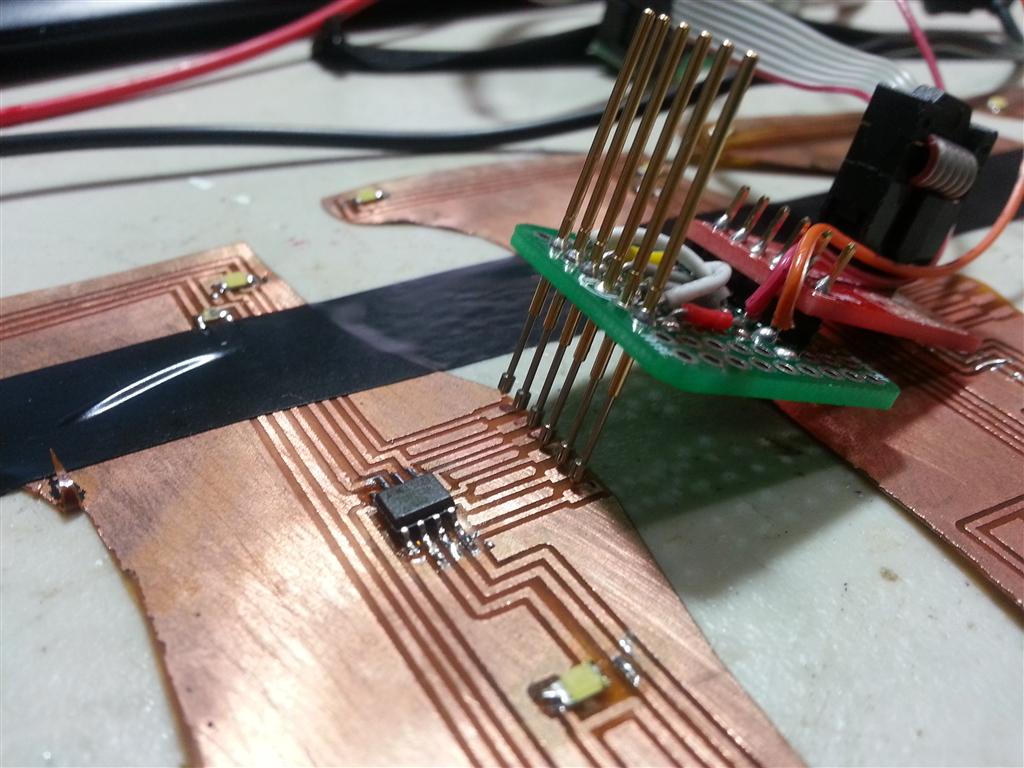
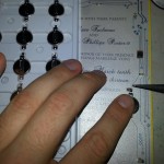
I had to come up with a way to program the AVRs once they were attached. I added a programming ‘port’ to the design consisting of pads off to the side of the controller. I built a crude jig that used pogo pins to contact the pads and connected to an AVR programmer. After the program was flashed and verified the port could be cut off.

Programming a card

Building the programming jig
Theory of Operation
The idea was to use the light sensor to detect when the card was opened. We toyed with the ideas of buttons and other ways to activate the card, but ended up settling with the light sensor. It’s assumed the recipients will be opening up the card in a moderately well-lit area so they can read it. The sensor is calibrated to trigger with those lighting conditions.
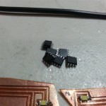
The cheapest AVR that still supports the C compiler I could find is the ATtiny13A. 1K of Flash and 64 bytes of memory was plenty just to flash some LEDs. To keep the design simple, there’s no hard off switch. Once the battery is attached to the card the AVR will always have power; so it had to be able to sleep to conserve energy.
When the controller is first powered it samples the light sensor. That sample is used as the threshold for activation from that point on; so final battery assembly had to be in the lighting conditions we wanted the cards to activate. Too dark and they would be triggered by the sun through the envelope, too bright and they wouldn’t come on when people opened them. It took a few tries of experimentation to find a good level of lighting. From then on all we had to do was solder the batteries to all the cards under those lighting conditions.
After the first calibration the programming enters a simple loop; check light, if above threshold play the light show; if not go to sleep. The light show is a set of fade values created by the ‘sparkle’ function in Vixen and saved to programming space. I used the same python script I created for the wishing well to convert the values. A simple software PWM routine handles fading the LEDs.
Sleeping the AVR ended up being a trick and a half. I ran into a few issues you will see in Lessons Learned. However I was able to get it to work. The AVR will deep sleep for 2-3 seconds before the Watchdog timer generates an interrupt to wake-up the core, test the sensor and then go back to sleep. While the card is ‘On’ it will drain the battery in less than an hour, the card ‘sleeping’ will last about a month.
Building the PCBs
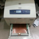
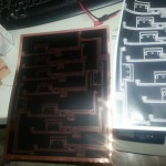
While I am a passionate at home engineer, I must admit I’ve never etched my own boards before; I’m too spoiled by inexpensive PCB services. So for this project I had to learn quickly. I read about a few people using Xerox solid ink printers to print mask directly onto copper-clad kapton tape and picked up one of the printers for $70 on eBay. I also purchased five 24″ x 18″ sheets of the copper clad kapton for $65 there as well. I cut each sheet into four 8.5″ x 11″ sheets to feed through the Xerox printer.

Copper clad in the paper tray
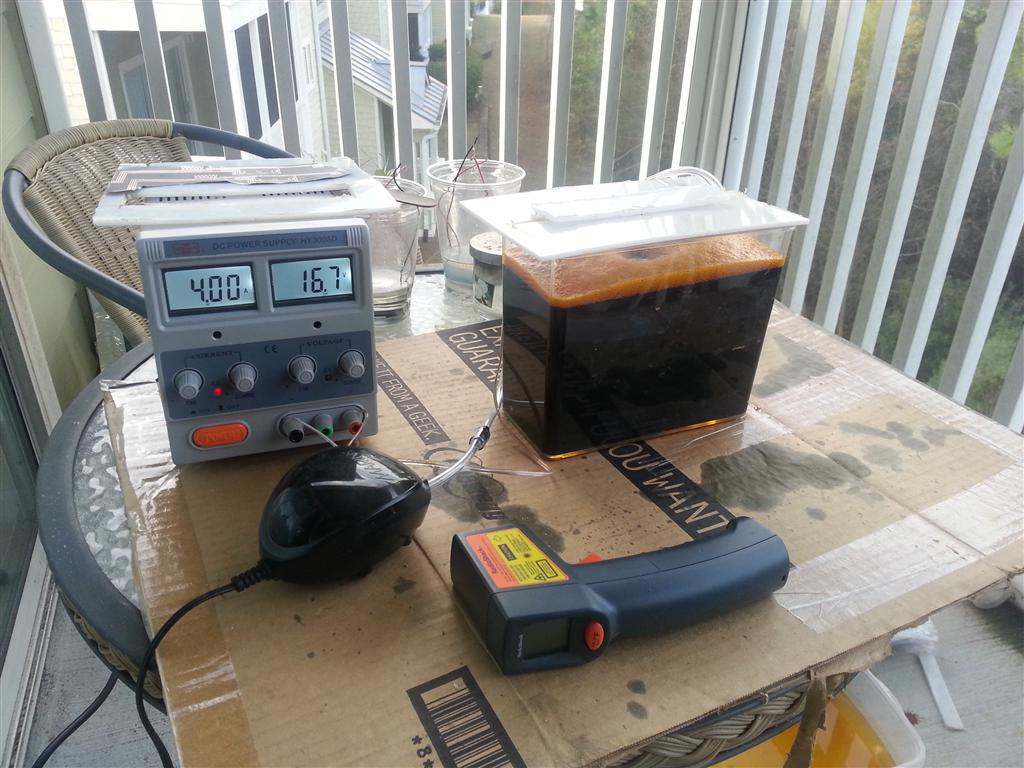
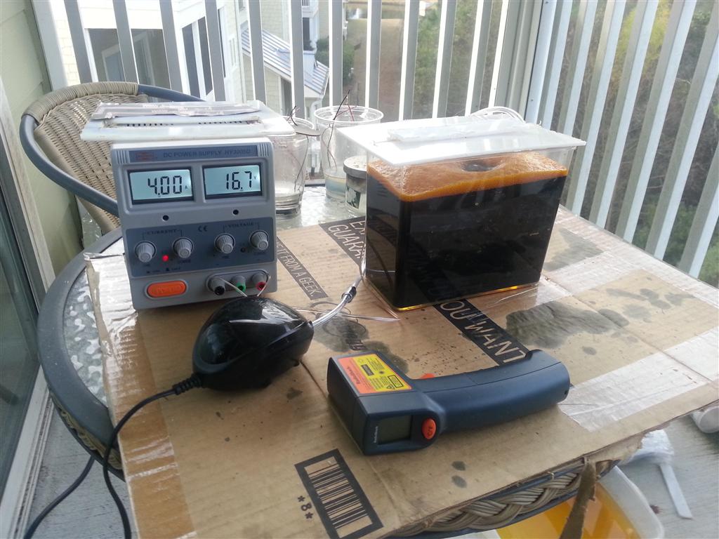
Next I had to build an etch tank. With speed and cheapness in mind, I went to the local pet store and bought a small specimen tank, air pump and air stone for $15 total. To heat the ferric chloride I soldered wires to a power resistor and epoxied the terminals to make them liquid tight. I then epoxied the air stone and resistor to the inside of the specimen tank.

Etch tank mark 1
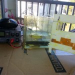
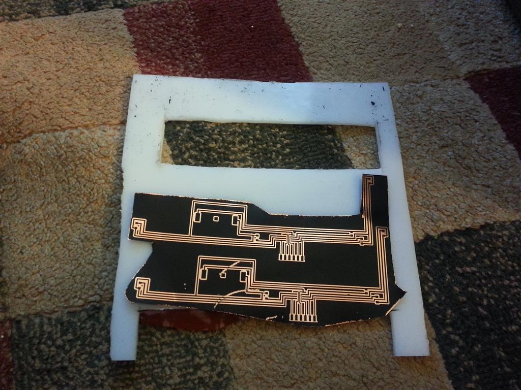
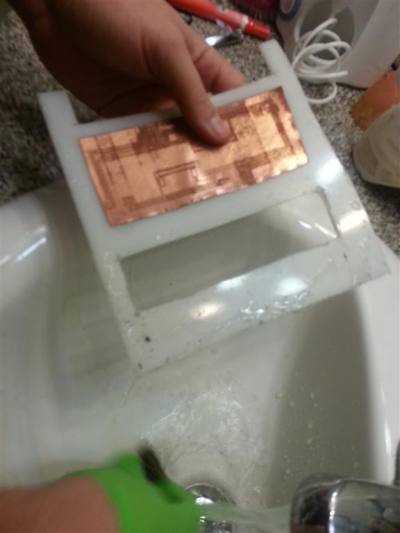
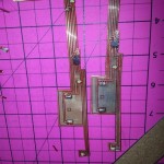
To hold the boards during etching I cut out a frame from HDPE plastic. The design allows fluid propelled by the air stone to flow around the center from front to back and top to bottom. I attached the copper clad kapton strips to the holder by double stick tape.

Attached strip to holder

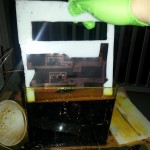
Heading into the tank

Etching
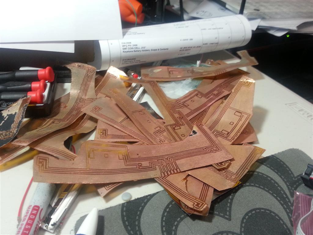
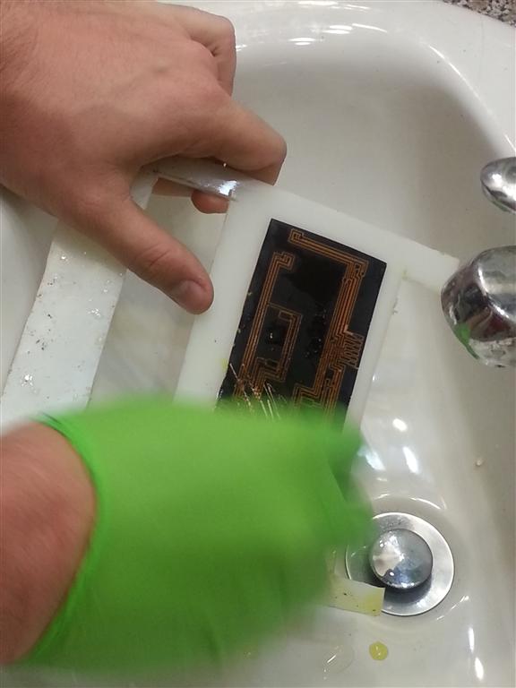
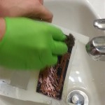
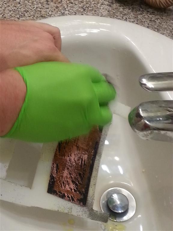
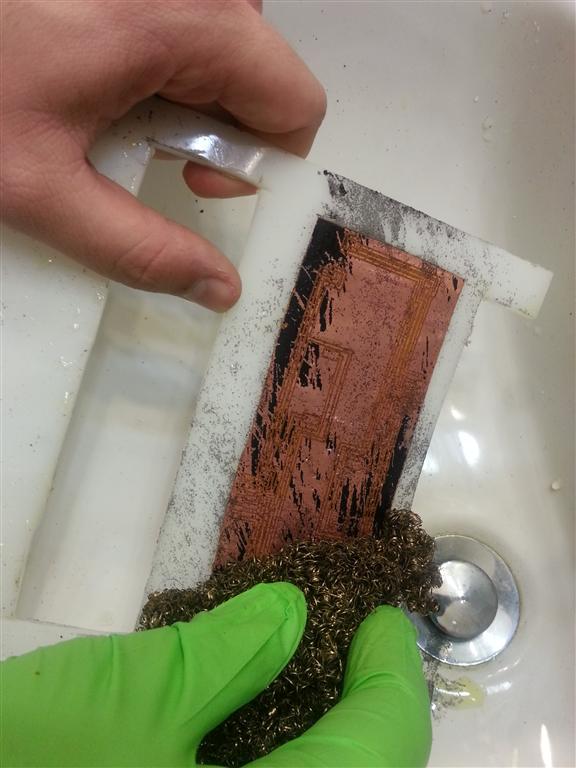
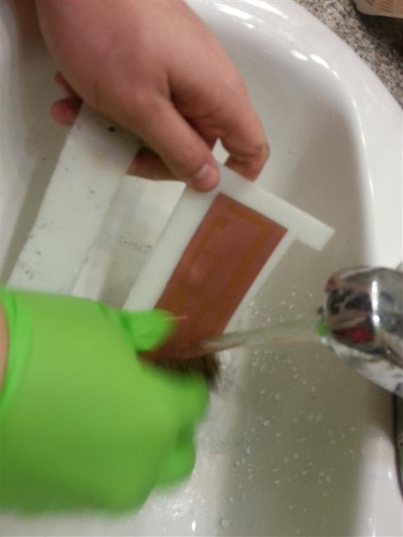
Putting about 20 watts into the power resistor brought the ferric chloride up to 100°F, and with the air pump circulating the fluid I could etch 4 boards in 25 minutes. A quick dip in a water tub stopped the etching and a cleaning with a Brillo pad removed the solder mask.

Cleaning off the etch resist

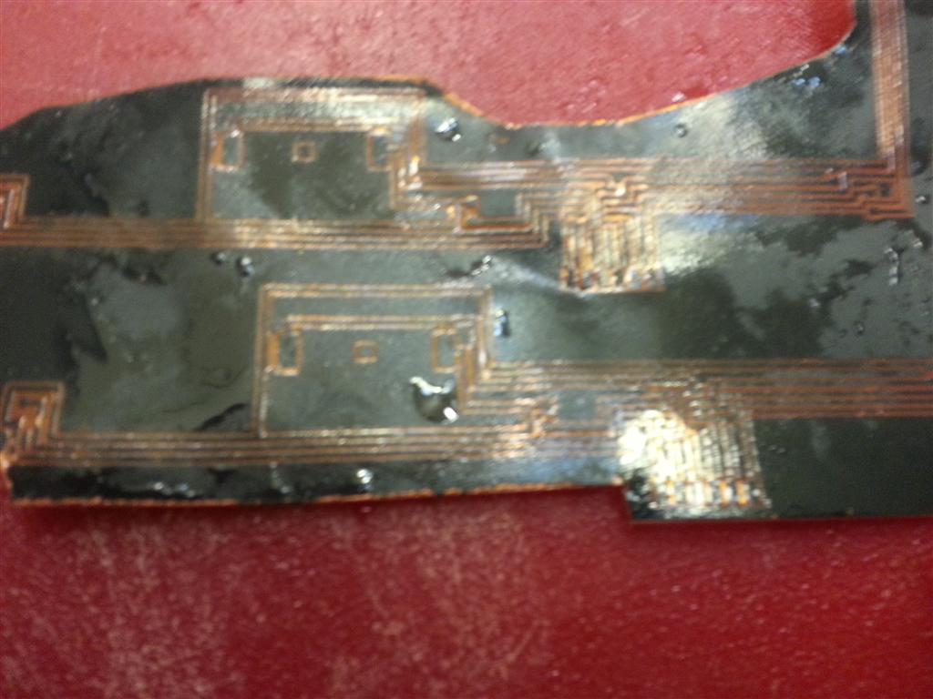
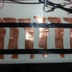
Before and after
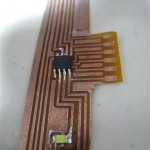
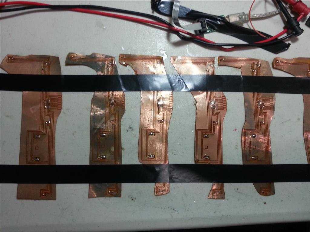
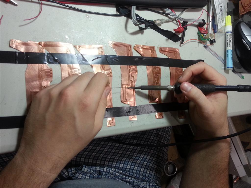
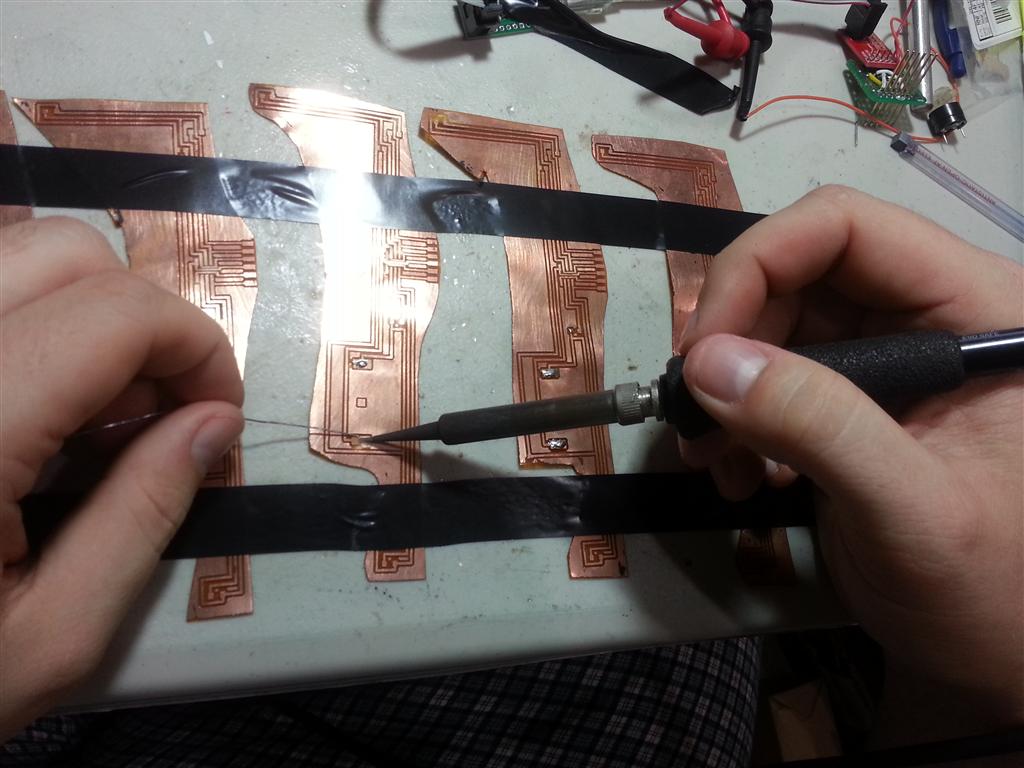
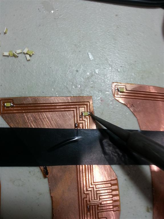
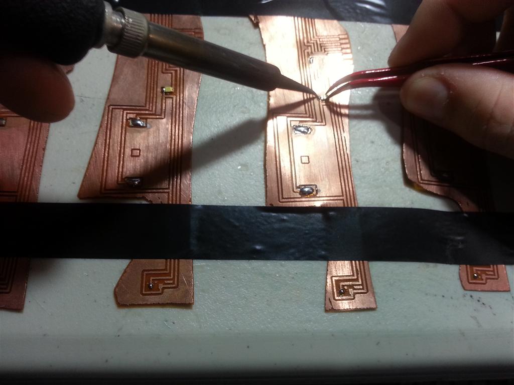
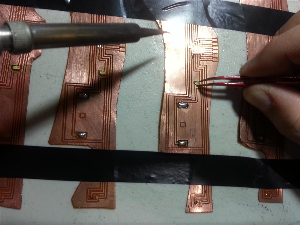
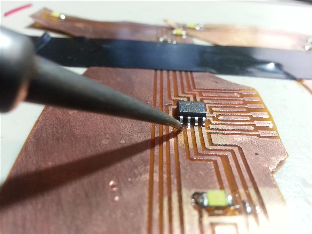
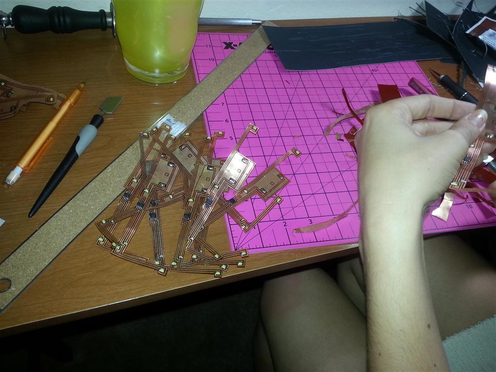
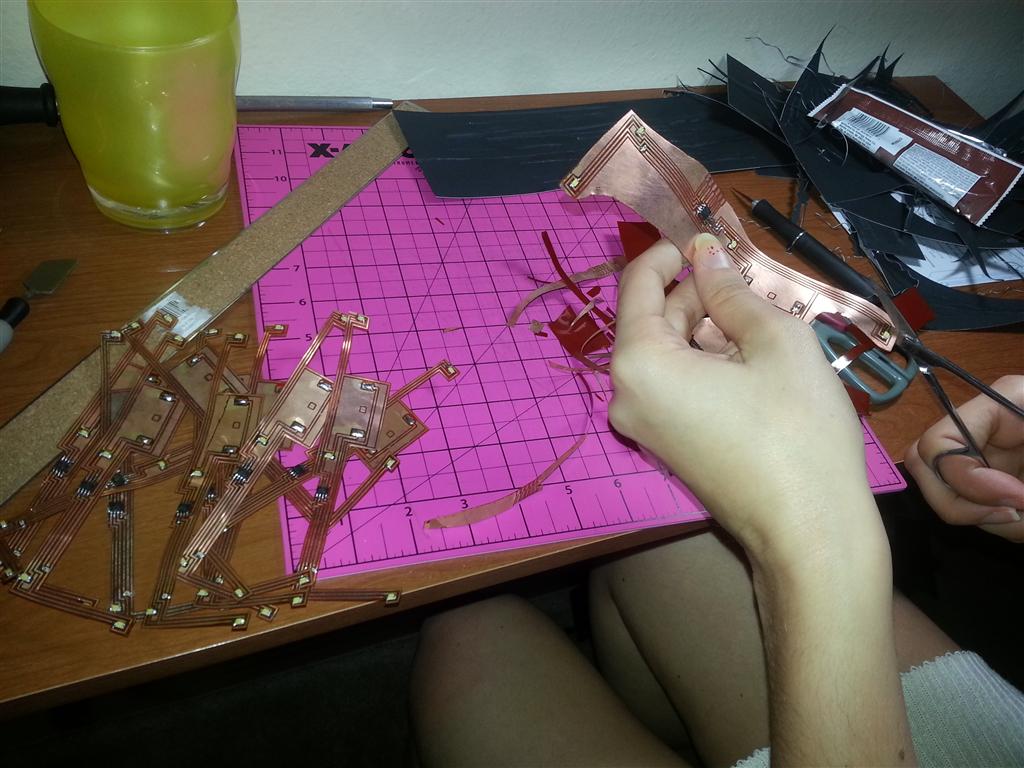
After allowing the boards to dry I cleaned all the pads with a flux pen (a very important step) and tinned each pad with my soldering iron. With 5 boards taped down to keep them secure I carefully soldered down each part, testing progressively as I went; except for the battery. I could finish and test about 5 boards every 30 minutes.

Assembly line

Fluxing

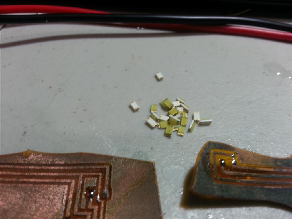
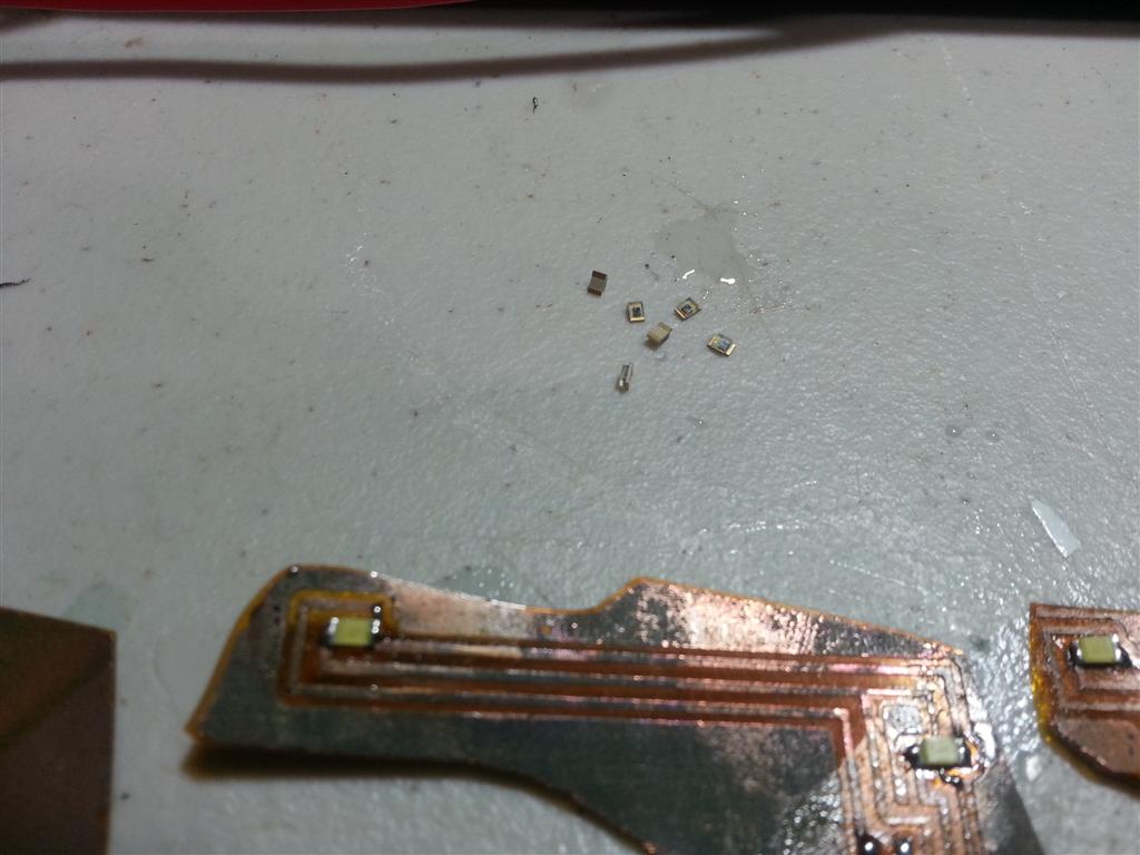
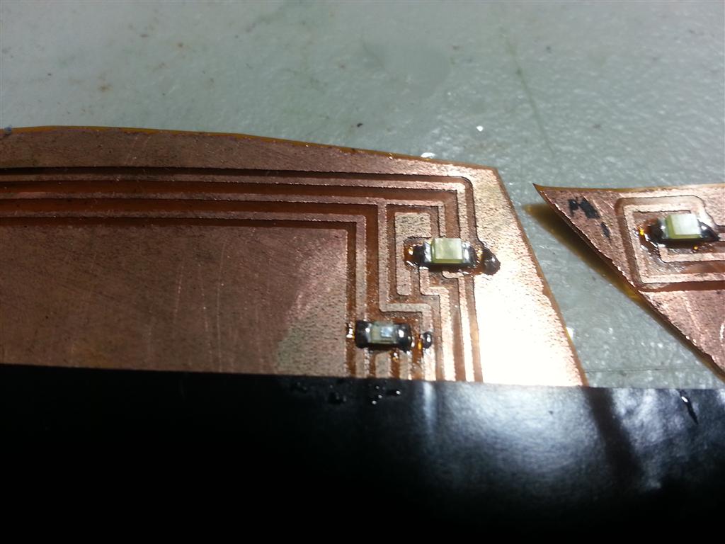
Soldering the parts on

AVRs go on next

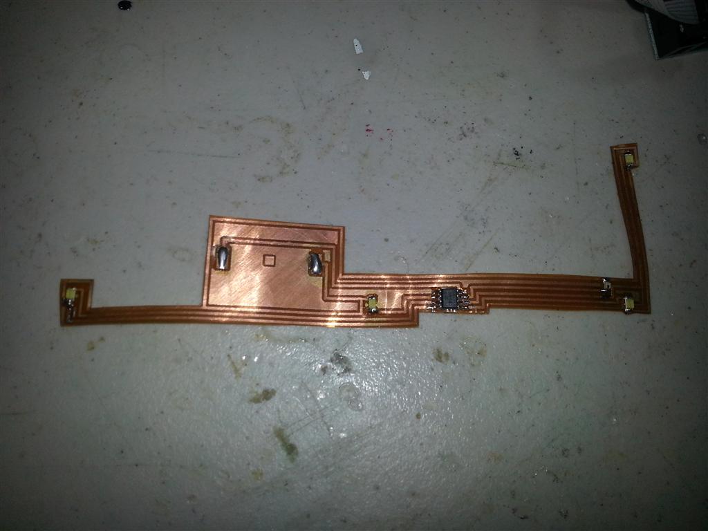
Done
Finishing the Cards
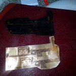
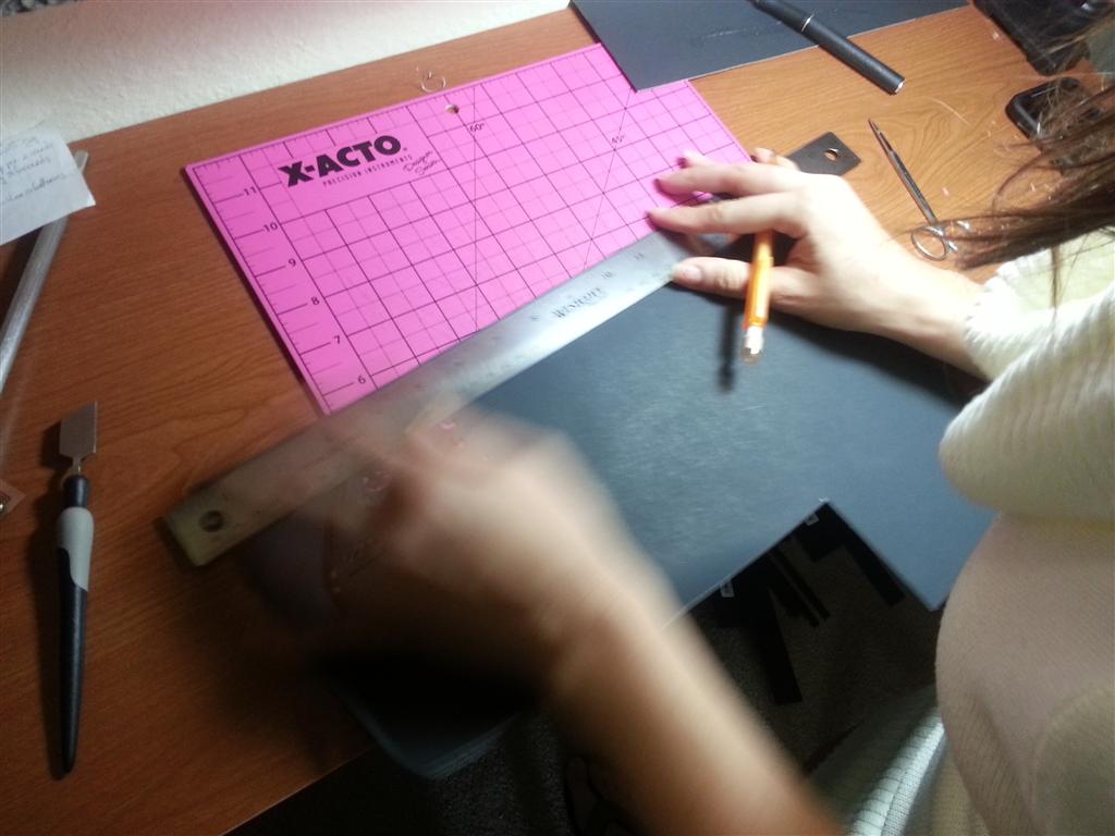
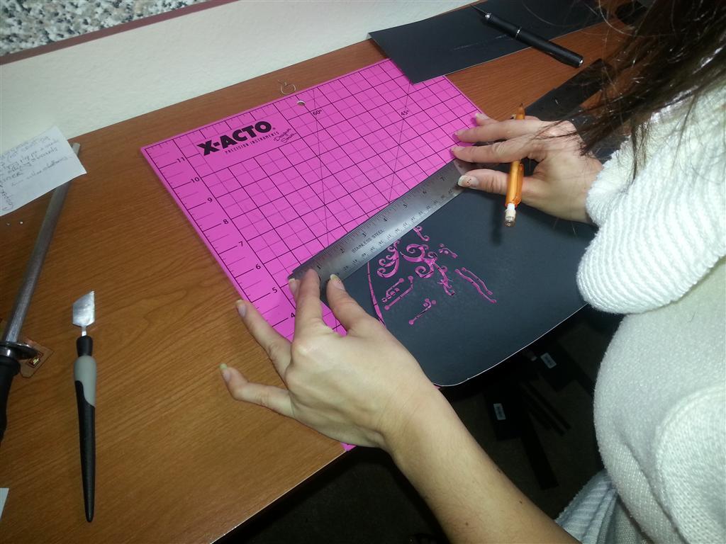
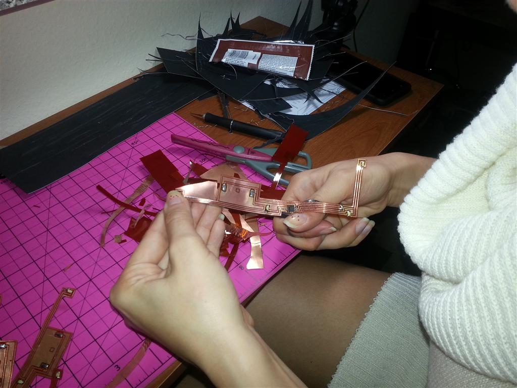
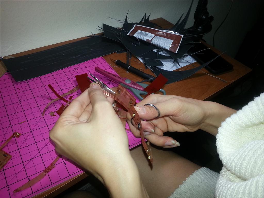
I handed over the circuits to Mara after they were populated so she could finish the cards. I bought her a new toy for Christmas, a Silhouette Cameo paper cutter. She put the new tool to good use on this project. The plan was to sandwich the kapton strip circuit between the forward facing card and the outer card stock cover. Mara had planned to cut the holes in the front card for the various components to pass through by hand. Instead she used the Silhouette’s precision homing features to cut the holes for us, two cards at a time; much faster than if we did it by hand.

Automated cut out holes, major timesaver

PCB attached to top card
She also designed the card cover artwork and cut it out with the Silhouette.

Cover artwork

Finishing touches

Finishing touches
Finally the battery was soldered on last just before getting mailing.

Installing batteries

Almost finished
Finished
Lessons Learned
- Print using Transparency mode
I learned after a couple of bad prints on the Xerox that you have to use “Transparency” as the paper type in order for the ink to adhere to the copper clad kapton. Anything else produces random results. I also haven’t figured how to clean off the ink from failed prints and reuse the copper clad kapton; the ink never adheres again.
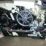
I also learned these printers will EAT ink every time they are power cycled. I had an issues where it started to refuse to print due to low ink but it was just a blockage problem. While finding and fixing the problem I wasted a lot of ink due to power cycling.

Impressive, but not easy to fix
- Seal the power resistor
After etching 60% of the boards my heating power resistor failed open circuit. When I drained the tank and removed the resistor I couldn’t find any damage. I did notice ferric chloride slowly leaking from around the two ceramic halves of the outer body. I can only conclude ferric chloride got into the resistor and ate away at the wire. I replaced the resistor with another one but this time epoxied around where the two halves meet to completely seal the resistor.
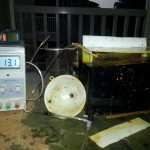
- Etching lessons
Etching my own copper was new to me and I had a few growing pains as a result. First lesson is that you need to watch your temperature like a hawk. I etched on my patio and the tank was exposed to the elements. Changing Florida weather threw a curve ball that I didn’t see coming. While it took 30 watts to maintain 100°F one day it raised the temperature to 130°F the next. The not so obvious to me at the time factor of course was the outdoor temperature. The spike in temperature caused the solder mask to melt away and turned the ferric chloride jet black.
Next lesson was when it was time to switch out for new ferric chloride. I assumed that it would just stop working, that it would not etch any more. Instead I just got progressively worse results; the mask was dissolving away in random spots while the copper failed to dissolve in others. Changing out the fluid corrected the problems.

Difference between old and new ferric chloride
- White LEDs are not good light sensors
My initial prototype used the light sensing properties of LEDs to sense light. However I got poor results. Different types of light produced different results and sunlight would activate the card no matter how many layers of card stock covered the card in the envelope. Research told the story. Different LEDs are sensitive to different wavelengths of light. While red and green LEDs are OK for sensing ambient light, white LEDs respond to UV light. This explained what I observed in my prototype circuit. I changed the design to include a phototransistor to sense the light level. I used the internal pull-up resistor in the AVR to bias the phototransistor which kept the parts count low.
- Trouble sleeping
I ran into a few issues trying to get the AVR to sleep properly. I wanted to use the watchdog timer to wake the processor out of deep sleep without resetting the core and wiping out the RAM holding the threshold value. I realize I could have used EEPROM to store the threshold and let the timer reset the core but I didn’t want to add more steps to final production (like shorting out an IO pin while resetting the core) to set the threshold value.
I found that the watchdog timer routines in AVRClib assumed you are using the timer to reset the core instead of just generating an interrupt. Just changing the bit that toggles the two modes after the timer is initialized produced strange results. I found deep in the AVR forums someone having similar problems who got it resolved by altering the routines from AVRClib to configure the timer in interrupt mode from the start. That produced reliable results in my case.
Dealing with ‘The Feds’
Yes, I’m aware I’m a Federal employee myself, so I can’t poke too much fun. But it means I also have learned to deal with rules, no matter how ridiculous they are. Shipping Lithium batteries via USPS became a lot more involved this past year and it took some time researching what those new guidelines mean. Then I had to consider what design changes could be made to follow those guidelines. Let’s start with the legalese: (and this is just the parts that relate to my case!)
349.221 Primary Lithium (Nonrechargeable) Cells and Batteries
For domestic mailings only, small consumer-type primary lithium cells or batteries (lithium metal or lithium alloy) like those used to power cameras and flashlights are mailable domestically under the following conditions. See 622 or IMM 136 when mailing batteries internationally or to APO, FPO, or DPO destinations.
- General. The following restrictions apply to the mailability of all primary lithium (nonrechargeable) cells and batteries:
- Each cell must contain no more than 1.0 gram (g) of lithium content per cell.
- Each battery must contain no more than 2.0 g aggregate lithium content per battery.
- Each cell or battery must meet the requirements of each test in the UN Manual of Tests and Criteria, part III, and subsection 38.3 as referenced in DOT’s hazardous materials regulation at 49 CFR 171.7.
- All outer packages must have a complete delivery and return address.
- Installed in Equipment. The following additional restrictions apply to the mailing of primary cells or batteries properly installed in the equipment they operate:
- The batteries installed in the equipment must be protected from damage and short circuit.
- The equipment must be equipped with an effective means of preventing it from being turned on or activated.
- The equipment must be cushioned to prevent movement or damage and be contained in a strong enough sealed package to prevent crushing of the package or exposure of the contents during normal handling in the mail.
- The mailpiece must not exceed 11 pounds.
Did you catch all of that? Let’s break these down a bit.
- Each cell must contain no more than 1.0 gram (g) of lithium content per cell.
- Each battery must contain no more than 2.0 g aggregate lithium content per battery.
Seeing as the battery weighs a little over a gram as a complete package, I’m sure there’s much less actual Lithium than that in the battery.
- Each cell or battery must meet the requirements of each test in the UN Manual of Tests and Criteria, part III, and subsection 38.3 as referenced in DOT’s hazardous materials regulation at 49 CFR 171.7.
Oh boy. I don’t even want to dive into that document. Since I received the batteries from a well know US distributor via USPS and the same rules under ‘General’ apply to uninstalled batteries I assume they would have confirmed compliance.
- All outer packages must have a complete delivery and return address.
Easy enough, we were planning to do that anyway.
Next is the section that applies to batteries ‘Installed in Equipment’.
- The batteries installed in the equipment must be protected from damage and short circuit.
- The equipment must be cushioned to prevent movement or damage and be contained in a strong enough sealed package to prevent crushing of the package or exposure of the contents during normal handling in the mail.
Alright, things are getting a bit complicated here because the rules are a bit vague. How do you quantify the acceptable level of ‘protection’? Are we talking a steal reinforced box? Or is a thin layer of paper good? Trying to settle somewhere in the middle was the goal. The battery is protected by two layers of thick card stock on both sides when the card is folded up in the envelope. I fell comfortable calling the battery safe from “normal handling” now.
- The equipment must be equipped with an effective means of preventing it from being turned on or activated.
More grey area. More-so than normal because of the way the card is designed to activate. Is a sleeping microprocessor considered ‘on or activated?’ Or since the card doesn’t ‘activate’ till it senses light can it be called ‘off’ in the mean time? How effective does the ‘effective means’ have to be? The black card stock and an envelope liner effectively keeps the sun from activating the card; so I’ll consider this one satisfied.
- The mailpiece must not exceed 11 pounds.
Not even close. Well, I think we meet all the regulations.
The Hidden Message
Now, of course I couldn’t leave a few hundred free bytes of flash leftover well enough alone. I decided it would be fun to throw in a hidden Easter Egg of sorts. Once the sparkle effect show is over, the light sensor is sampled again. If the level is below the threshold (if something like a thumb is covering the sensor for instance) than the code starts a different routine; a message is flashed out in Morse code.
I coded a simple routine that adheres to Morse timings and reads out a message saved in program space. What does the message say? Well, I’ll leave that up to you to decode.
Source Code
Source for the program running on the AVR as well as the board design can be found on Github for download.
Gallery
-
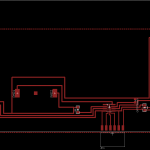
- Board layout before Photoshop streching
-
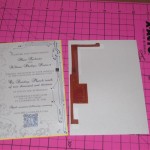
- PCB attached to top card
-
- Done
-
- Early revision
-
- Etch tank mark 1
-
- Impressive, but not easy to fix
-
- Copper clad in the paper tray
-
- Before and after
-
- How many do I have to make again?
-
- Panelized design

-

- Finishing touches

-
- Almost finished


-
- Attached strip to holder
-
- Heading into the tank
-
- Etching
-
- Cleaning off the etch resist
-
- Assembly line
-
- Fluxing
-
- Soldering the parts on
-
- AVRs go on next
-
- Finishing touches

-
- Difference between old and new ferric chloride
-
- Installing batteries


-
- Inside finished card
-
- Front cover
-
- Simple design

-
- Cover artwork
-
- Automated cut out holes, major timesaver

Trackbacks / Pingbacks