
Our Geeky Wedding – DIY 3D Printed Geek Wedding Table Centerpieces
Posted in Projects, Wedding by Bill
24 Mar 2013

Well, I’m pleased to say the #GeekWedding was a success and I am now a married man. The 3 weeks leading up to our wedding turned into a hack-a-thon of custom DIY projects we’ll be posting about over the coming months. We are going to wait out the 5-8 weeks it will take to get our wedding pictures before we post about many of the projects, but for a few we have enough media on hand to post about now. First up is our DIY custom 3D printed wedding centerpieces.
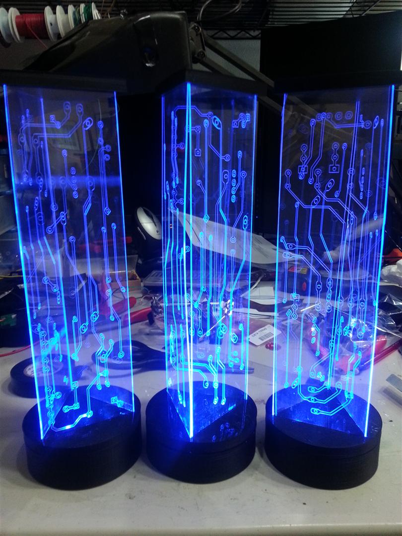
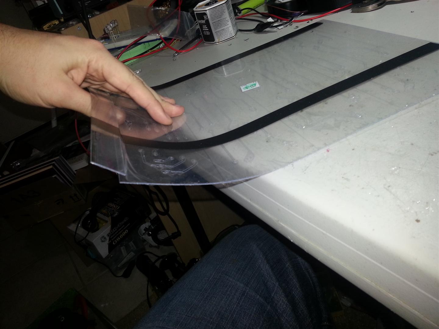
We got dangerously close to our wedding day with only vague ideas on how we were going to decorate our tables with our ‘Circuits and Swirls’ theme. The table cloths already incorporated a swirls element, but there was no circuits to be found. Then this idea came to me. We are both a fan of blinky things (wait till you see our wedding attire) and I knew edge lit plastic engraved designs always look cool. But how could we make something at home on the cheap? First I tackled the engraved plastic part. I ran to the craft store and found thin plastic sheets. I ran these sheets through Mara’s Silhouette paper cutter a few times and found it could score the plastic enough to diffuse light.
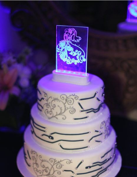
Next I needed structure to house the power source, LEDs and plastic sheets. I sat down with Autodesk Inventor and came up with some prototypes. The ends result is 5 pieces that come together to form a single centerpiece. I had to build a dozen of these things, so I incorporated a few tricks to make them easier to build. Below is the design. The end of the posts shows a matching cake topper we made even closer to the wedding.
The Design
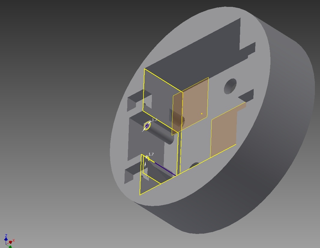
Base piece.
I had to take into several factories during the design and prototyping of our centerpieces. They needed to be cheap and easy to make. This was a last minute project and we were short on time and money. It might have helped if I was more proficient at 3D CAD, or formally taught mechanical engineering in any sense. Regardless, this EE got the job done, though I’m sure not in the most elegant way. I wanted to make the design ‘snap’ together so it would be easy to make. It took a few tests prints until I got the dimension tolerances just right on my 3D printer to make that happen. All 5 parts needed to make a centerpiece were designed in Autodesk Inventor and printed on our Makerbot Thing-o-matic 3D printer.
The LEDs strip were leftover from my best man Dan’s latest project and were a perfect fit for this application. The batteries were removed from packs meant for cable modems. I just happen to have a whole box of these packs lying around. I already had the plastic filament for the 3D printer and scrap wire. All we had to buy to make these centerpieces was plastic sheets from Hobby Lobby for $1.67 each and switches from Mouser for $0.71 each. Not bad for a tight budget.
All the 3D files and our Silhouette files can be found here on Thingiverse.
My hope in posting this is people can change the design on the sides and make their own awesome edge lit centerpieces to match any occasion. The rest of this post will read like assembly instructions for the centerpieces for anyone who tries to make their own. Even if you don’t have access to batteries like mine the base will hold a 4x AA battery pack and a voltage booster (to get 12V). The centerpieces were such a hit we had several guests ask if they could take one home. We said no, but still 2 were taken anyway. Since they have served their purpose and family expressed such an interest in them, we’ve decided to retrofit a regular AA battery pack in place of the Li-Ion batteries and send them out as gifts to our family. If you don’t have access to Li-Ion batteries like we did, skip the Li-Ion battery section if you are building these centerpieces.
But I want to buy some from you!
We have gotten a ton of these requests. These were a labor of love, it takes about 10-12 man-hours to make one centerpiece from start to finish. While the parts are cheap, our time is not. If you are interested in buying some, realize the price we may ask will be around $100 each depending on any modifications requested. If you are still interested, email me at the address on the bottom of the page.
Creating the Clear Plastic Sides
This is where Mara’s Silhouette paper cutter came in. The design is ‘carved’ or scored onto the plastic sheets by the cutter.
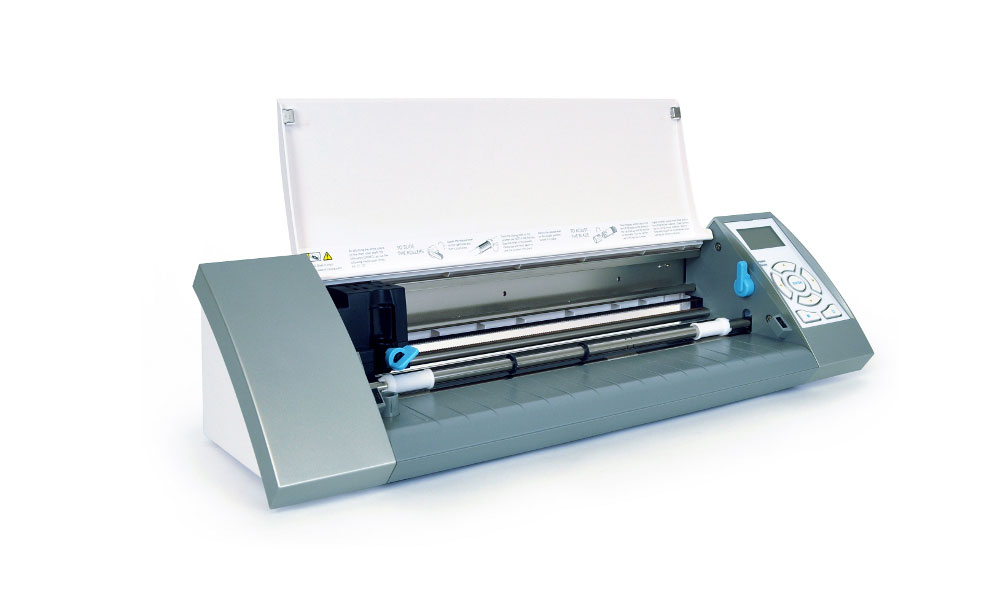
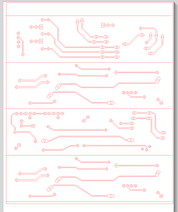
After some failed attempts, we found a knife setting of 7, speed setting of 1, and a thickness setting between 26-28 worked best at carving or scoring the plastic sheets. Each sheet produced 4 sides, and each centerpiece only needed 3. The Silhouette also scored straight lines onto the plastic to allow us to snap the sides apart during assembly. Below is the pattern we created for the Cameo:
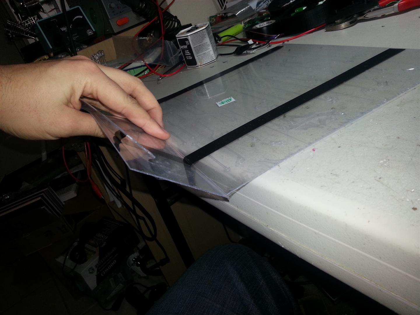
We found the bottom rollers on the Cameo would leave an imprint in the plastic after cutting. To mediate this problem we used electrical tape to ‘cushion’ the pressure from the bottom roller. You can see the electrical tape in the picture below:
Making the Battery Packs
The following is what we originally did when built the centerpieces. If you don’t have access to these types of batteries, skip below where we retrofitted in regular AA batteries.
I have a box full of Lithium Ion battery packs mean to be used in Arris cable modems. These are the same packs I used during the Build your own battery pack tutorial. It is overkill to use these 2.2Ah 18650 cells cells to run 20mA LED strips but since I already had all these batteries lying around it would be foolish to buy new batteries for this project. I charged them up before separating and building the battery packs.
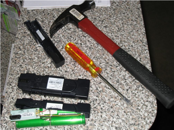
Removing the cells from the proprietary battery pack.
After the cells were removed from the original battery pack, it was just a matter of wiring 3 in series to give me ~12V.
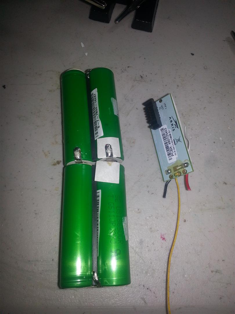
Cut off the original protection board.
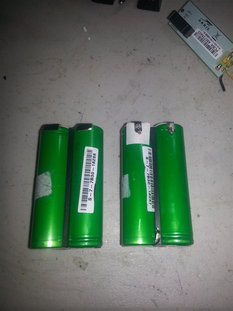
Separate the cells.
Match 3 in series.
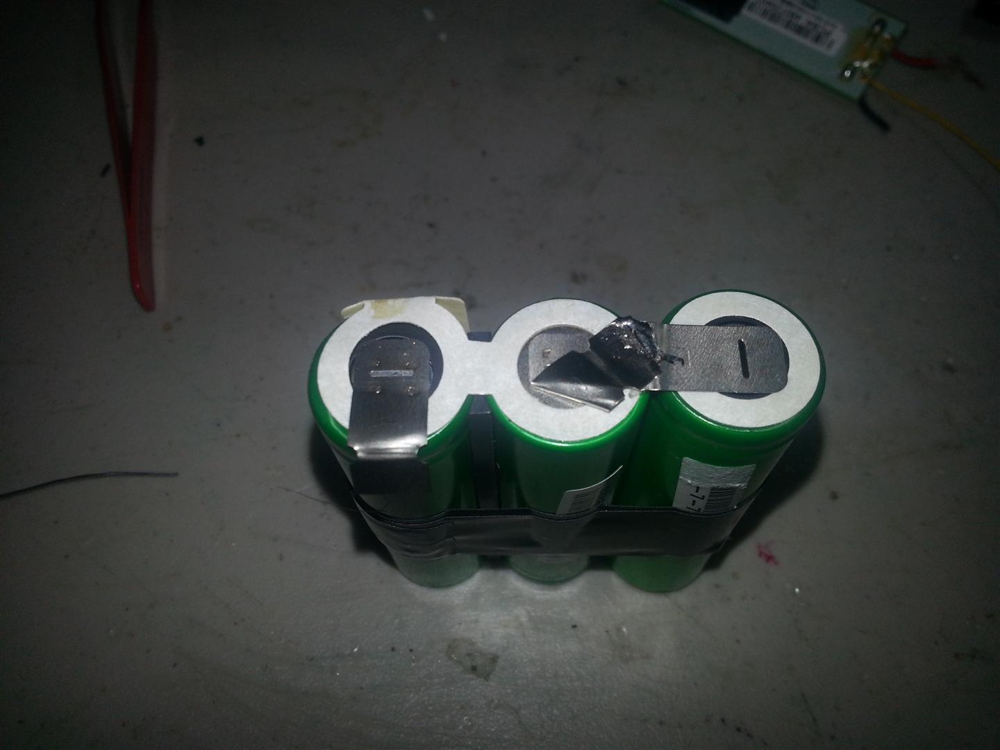
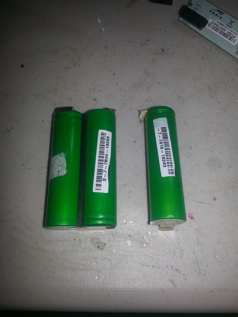
Solder 3 in series.

Before and after.
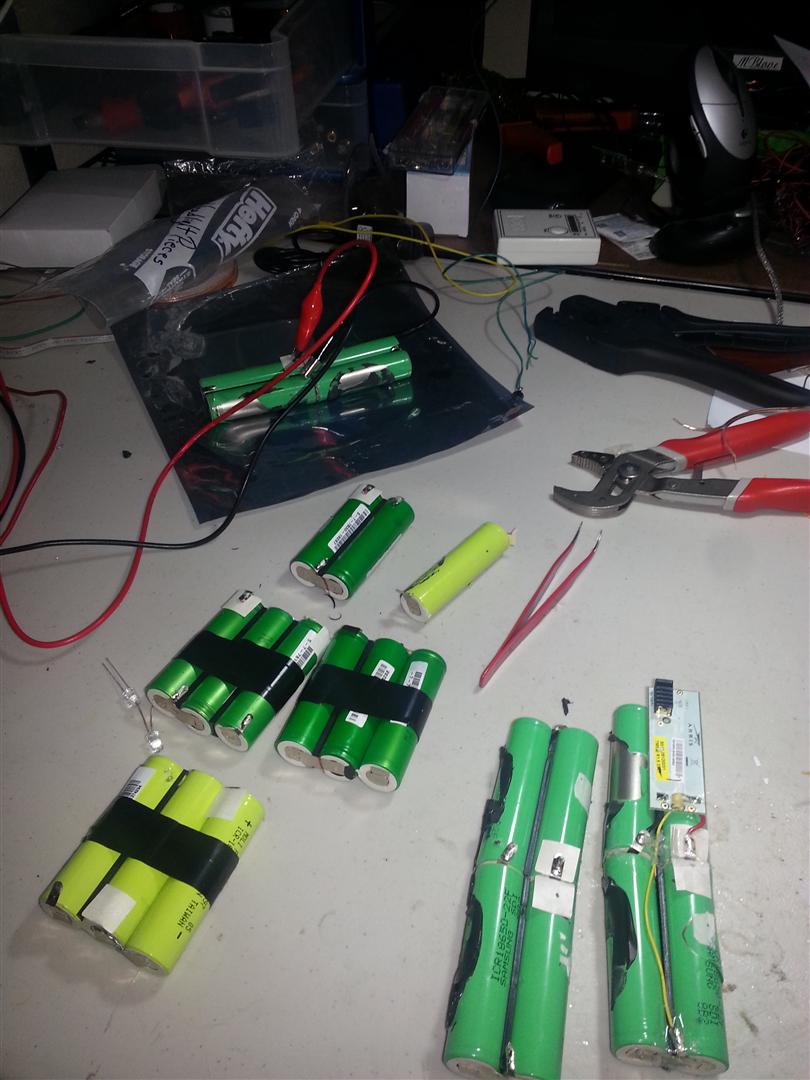
I had to build 12 battery packs!
I tried my best to build packs of similar model cells. You can see in the last picture I was running into a variety of colored wrapped cells inside the modem battery packs.
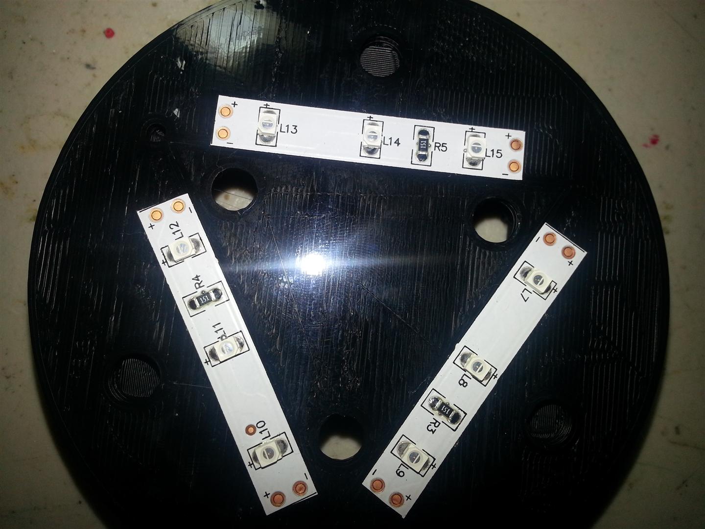
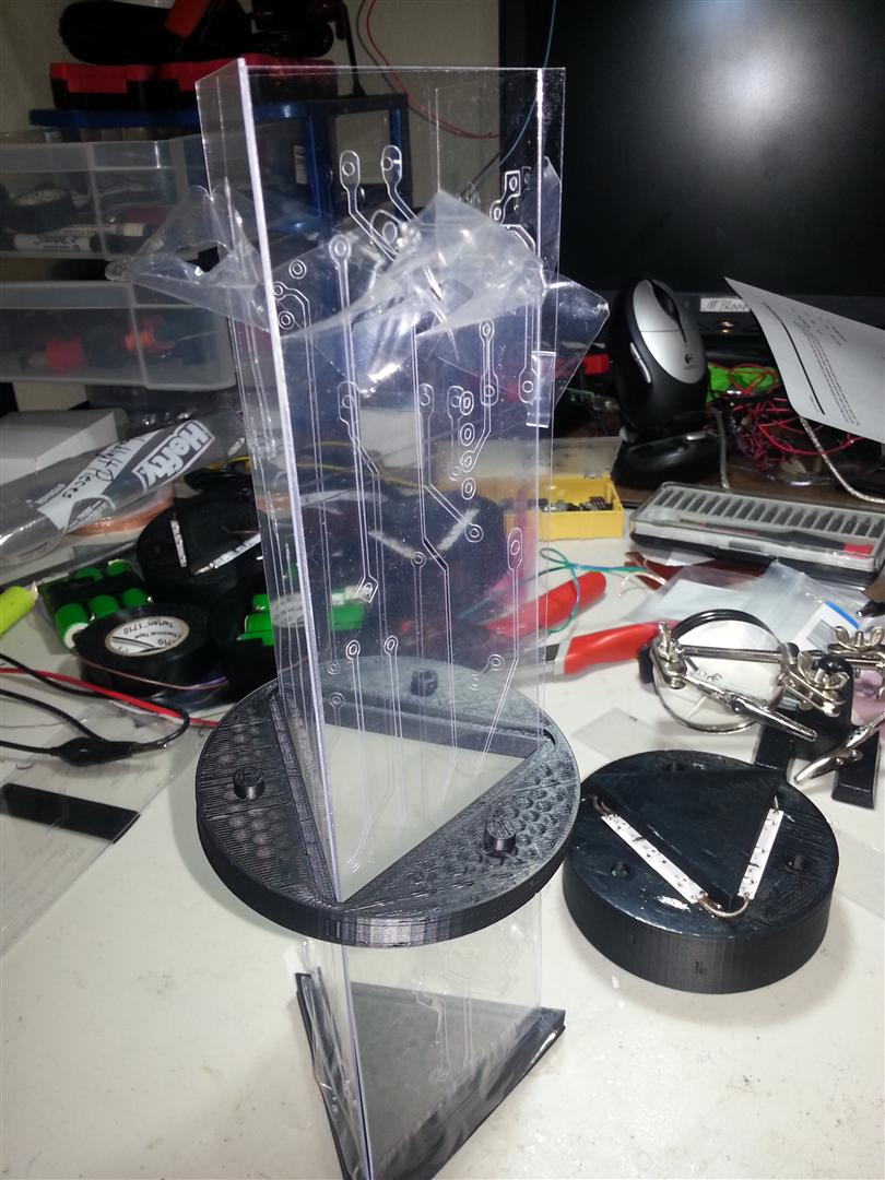
Wiring up the Base
Each centerpiece takes 3 segments of the LED strip. The segments need to be wired to the battery. Since they have solder pads on both sides of each segment, I used small gauge speaker wire to connect the segments together and to the battery through a on/off switch. Take care to observe polarity (+/-) of the LEDs. Make sure all the pluses (+) get connected together and connected to the plus side of the battery. Same for minus(-).
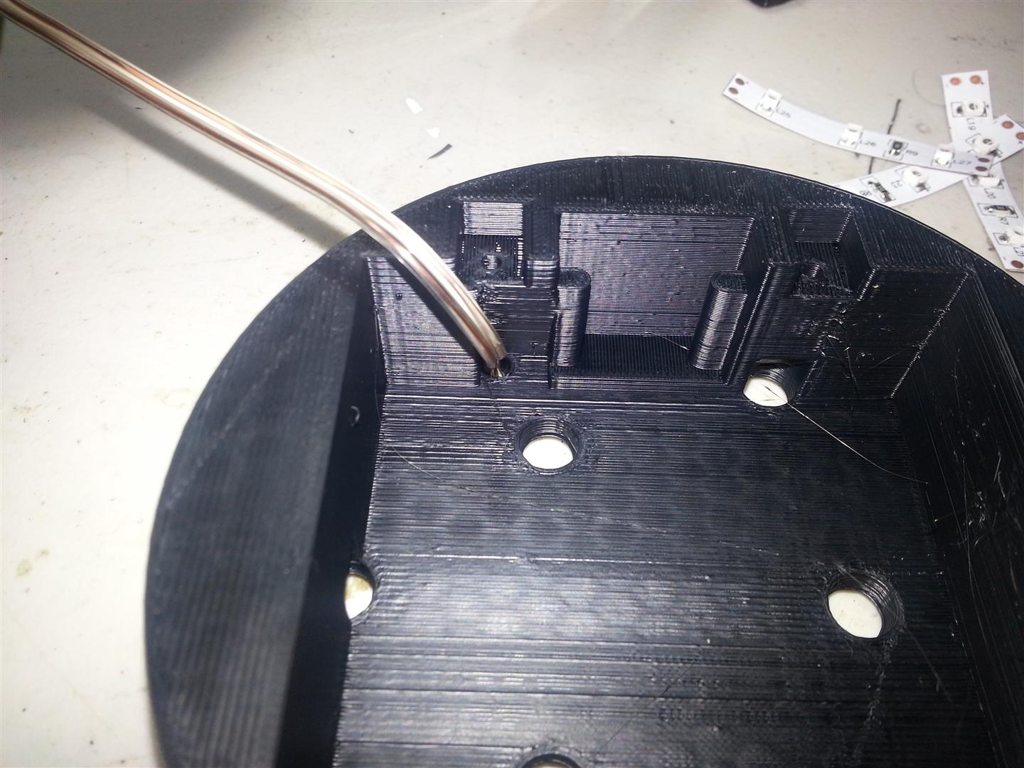
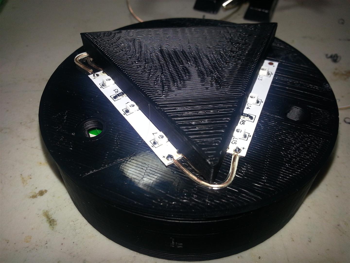
The design for the base pieces includes a very small channel along the top surface. This causes the 3D printer to layout seemingly useless lines around the center of the base. These lines are where the edge of the LED strips need to lie in order for the LEDs to line up with the edge of the plastic sides during assembly. This made assembly much easier.
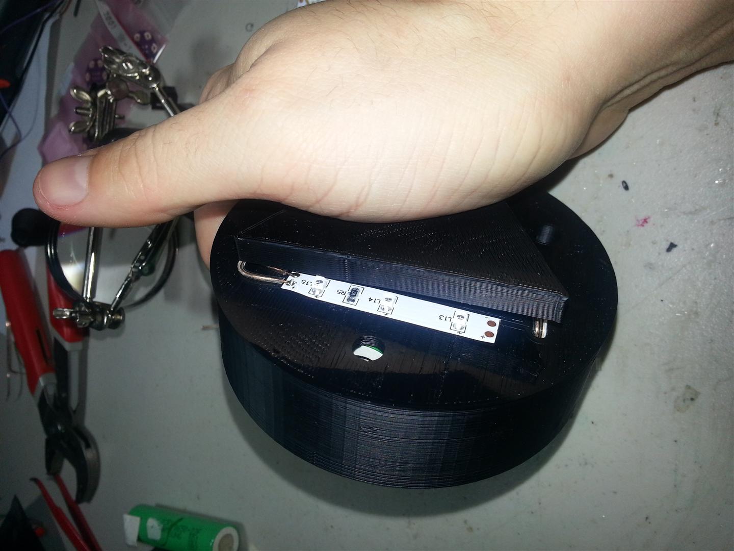
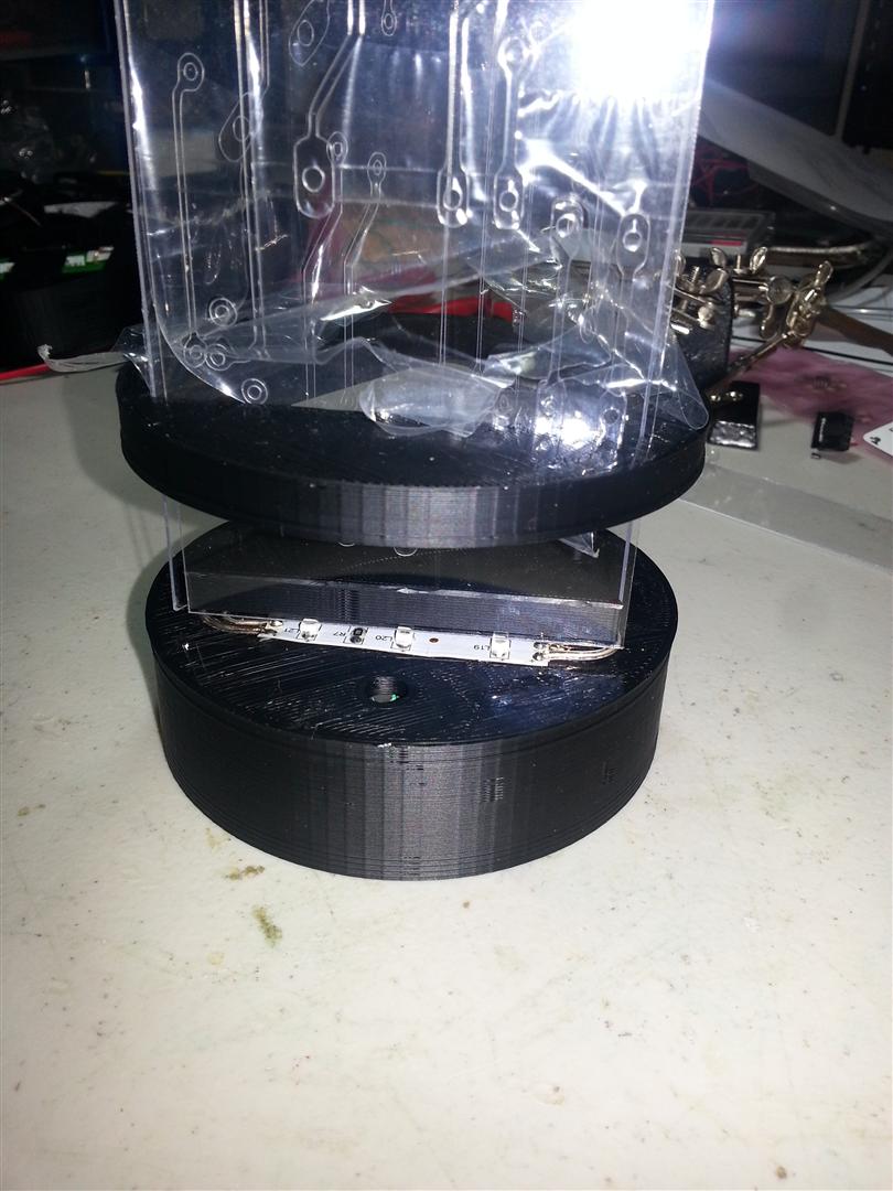
Self adhesive LED strips adhered to the base. Edges lined up with marks on 3D part.
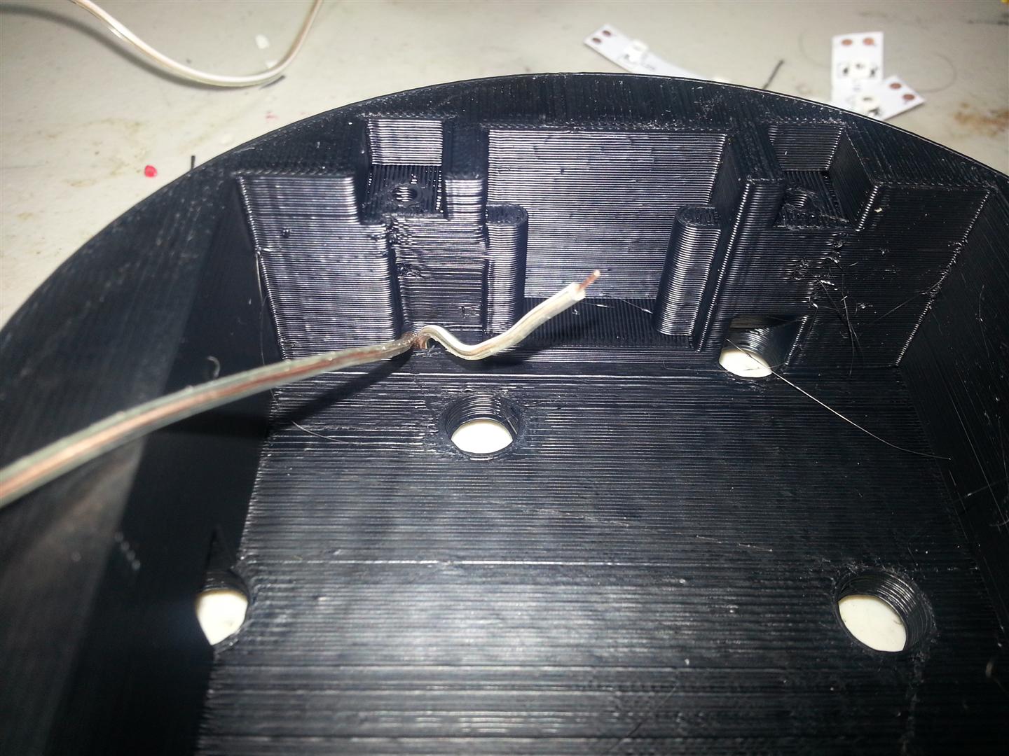
A single hole is located on one corner for a longer piece of wire to be fed through to underside where the battery pack will be kept.
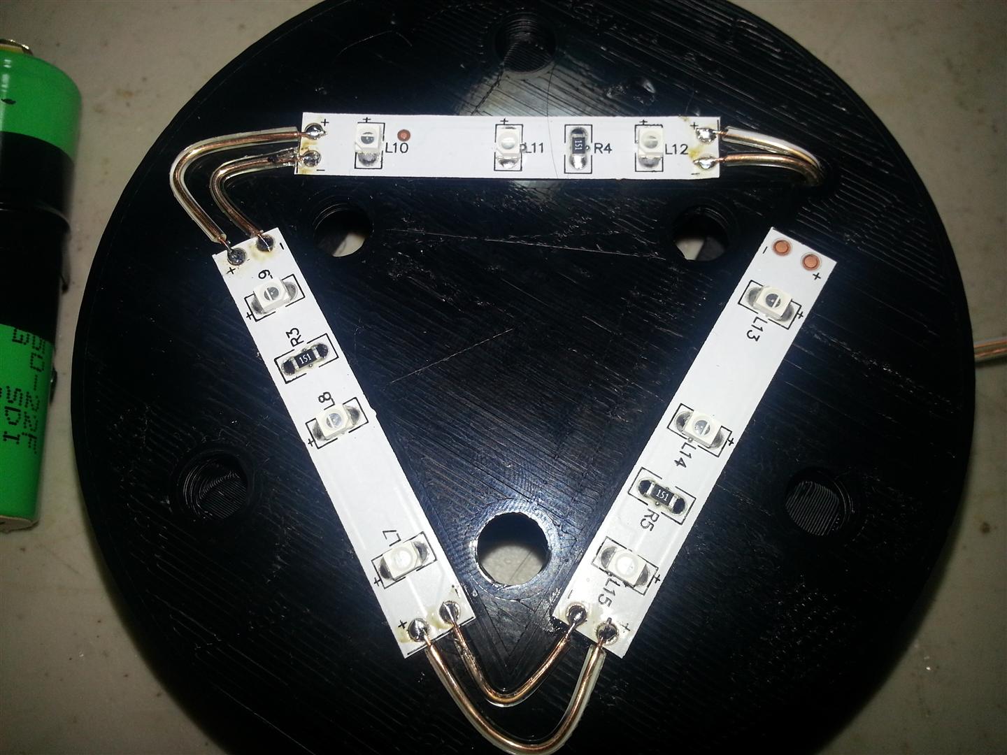
Strips connected by wire and a longer piece fed through to other side.
Wire coming out the bottom.
Next step is to add and wire in the on/off switch. If you are going to be using a AA battery pack, skip to the next section to see how to wire it in.
Start be cutting short one of the wires coming from the LEDs and solder it to one side of the switch. Solder the extra wire to the other.
Cut short.
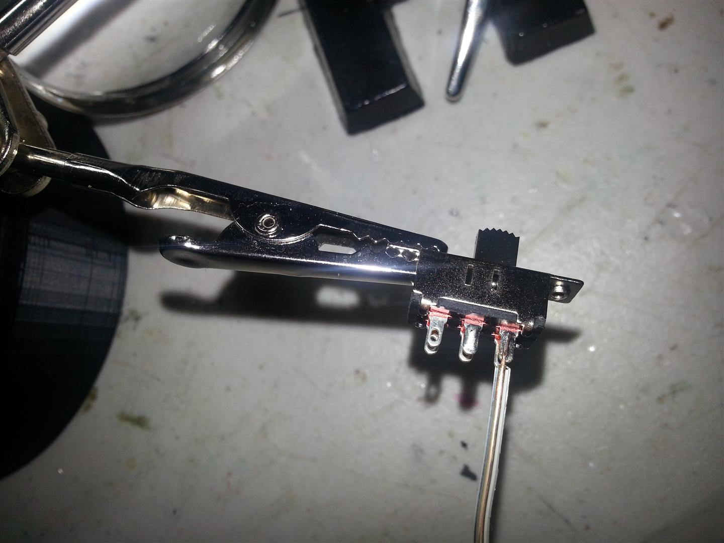
Solder to switch.
Solder extra to other side of switch.
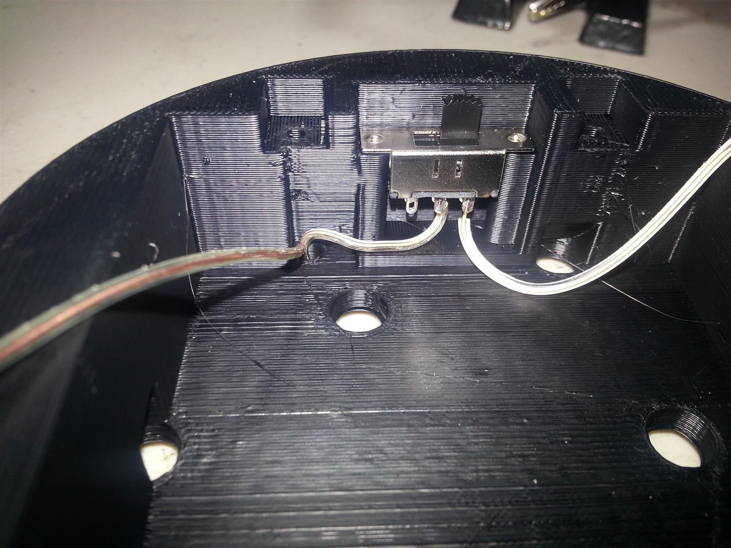
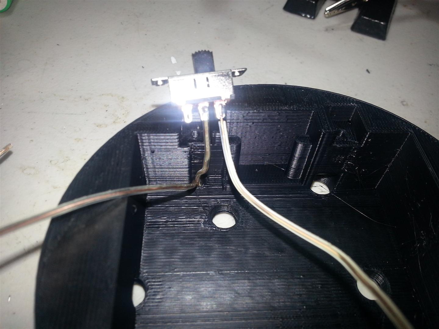
Push into switch socket.
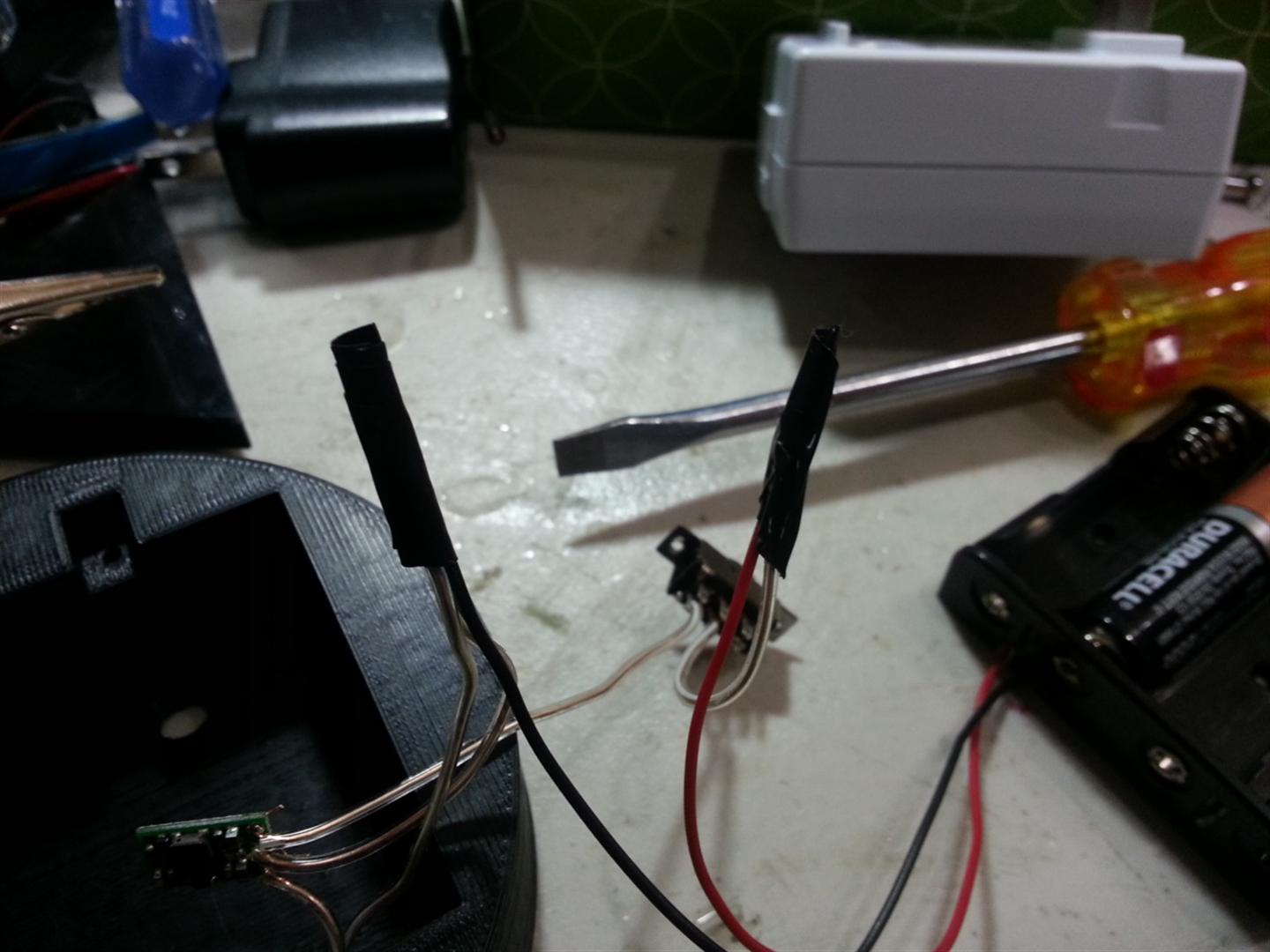
Next it’s time to solder the wires to the battery pack. Take care not to short the battery pack at any time.
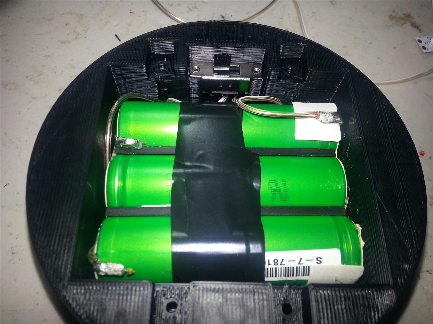
Soldered to battery pack and pack inserted.
Finally cover the batteries with the 3D printed cover. This cover has holes for screws and also holds the switch in position. In my case since the cover is slightly bigger than the compartment the cover snapped into the base and didn’t need the screws.
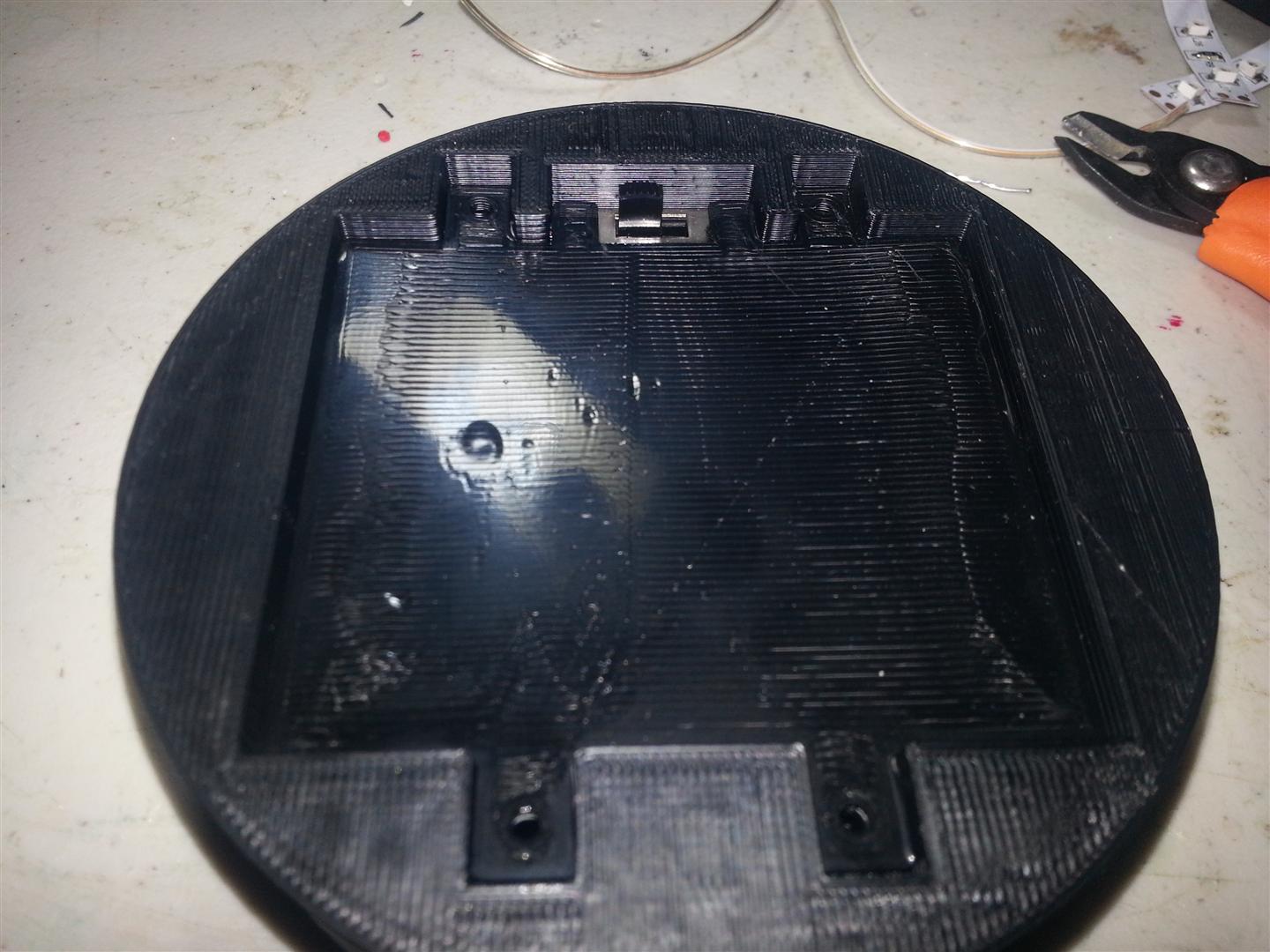
Battery cover.
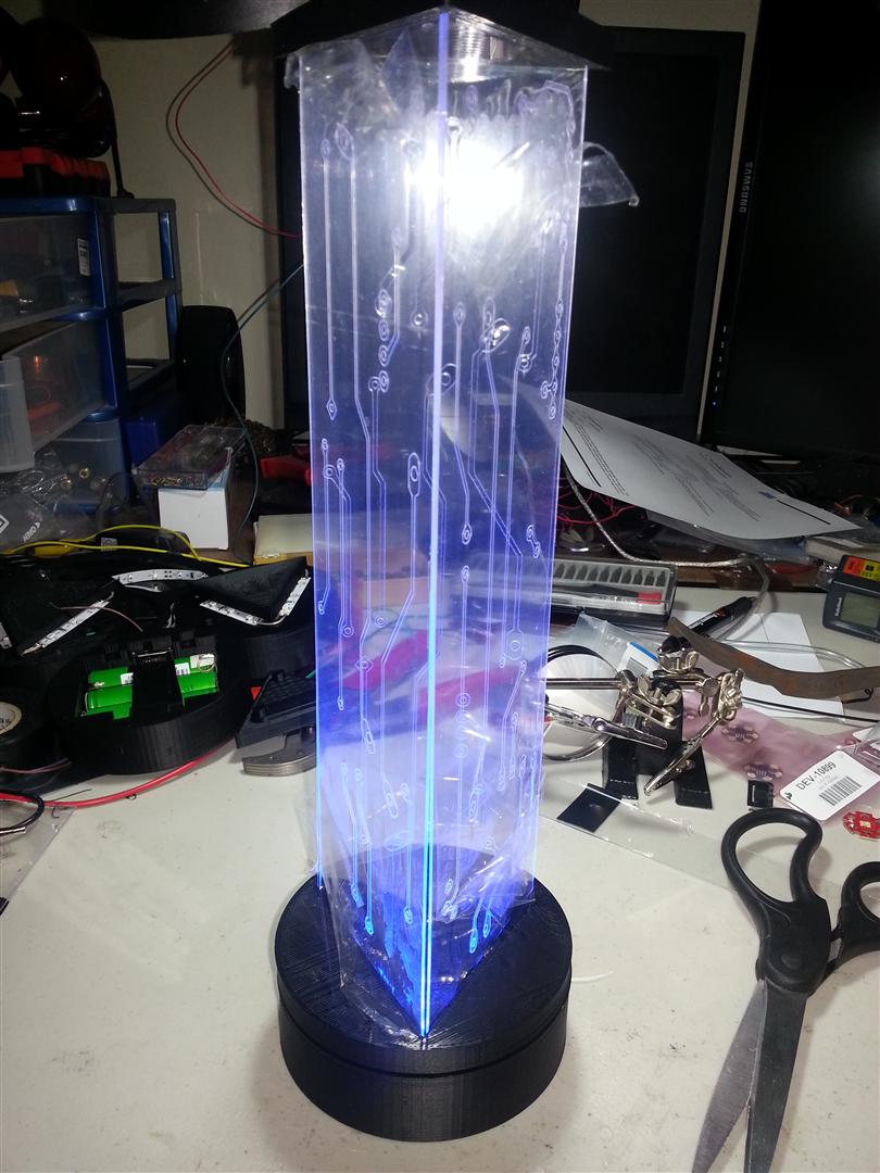
Now the base is complete.
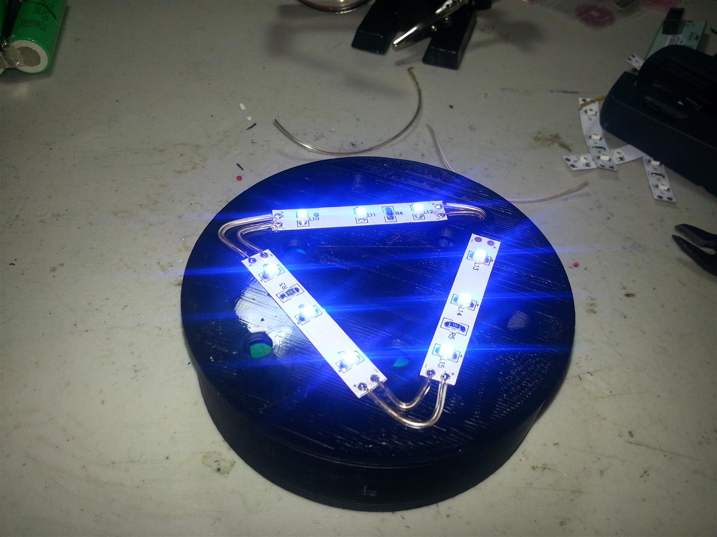
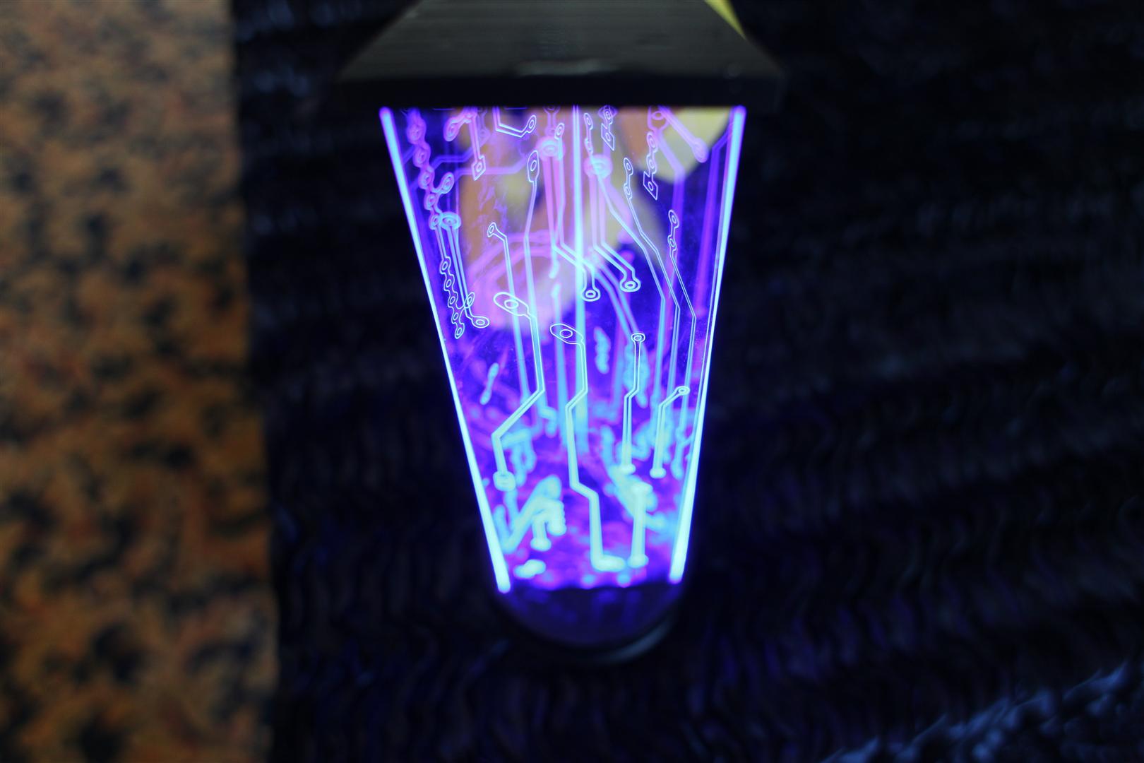
Completed base with blinding LED light.
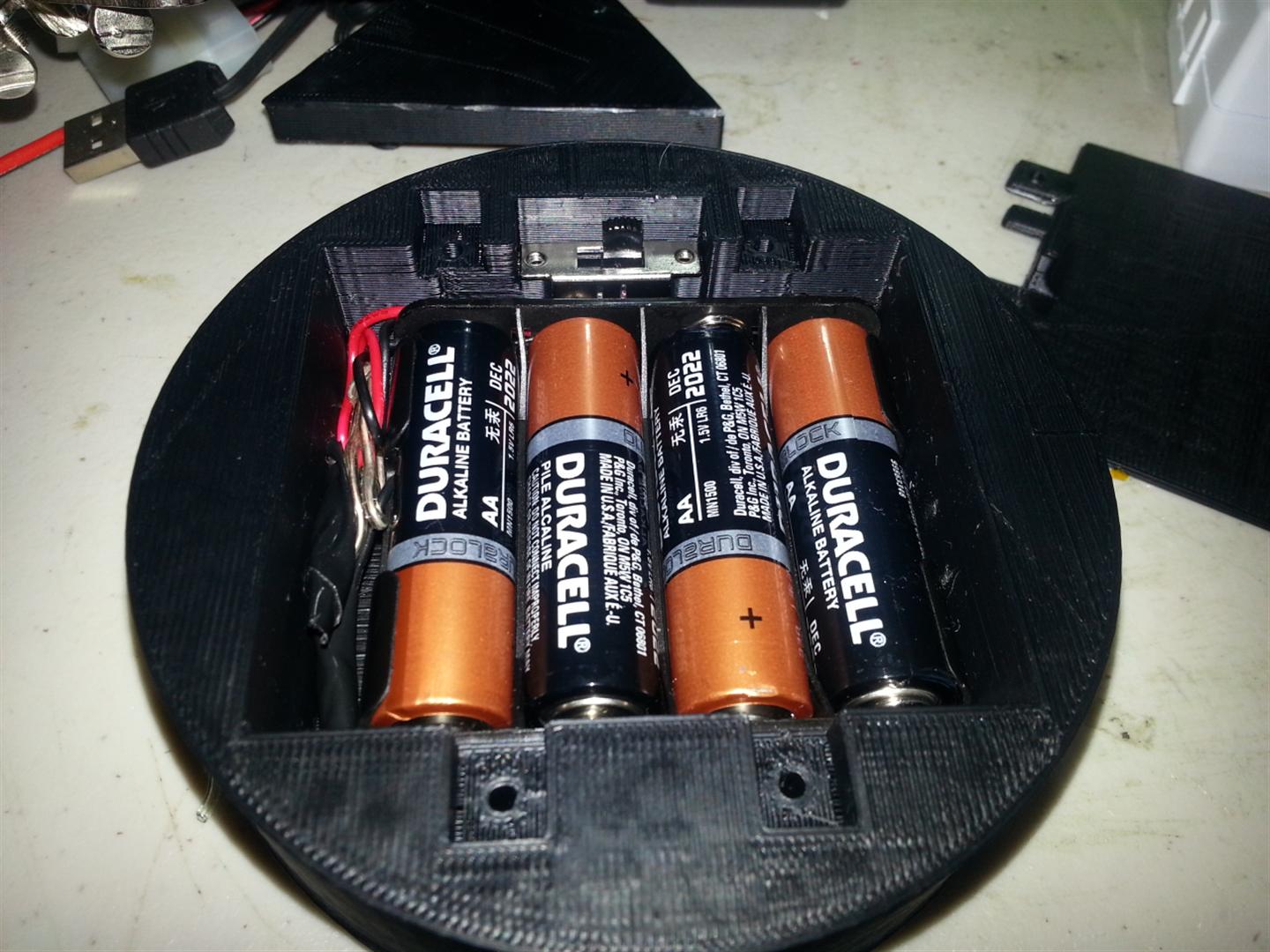
Converting for AA Battery Use
The centerpieces were so popular we’ve decided to give them out as gifts. However, bare Li-Ion cells aren’t friendly to an end user. So we took out the cells and put a AA battery pack and voltage booster in instead. We got the battery pack here and the voltage booster here.
The wiring is a bit different with the voltage booster, so to help I drew a bad wiring diagram to show you:
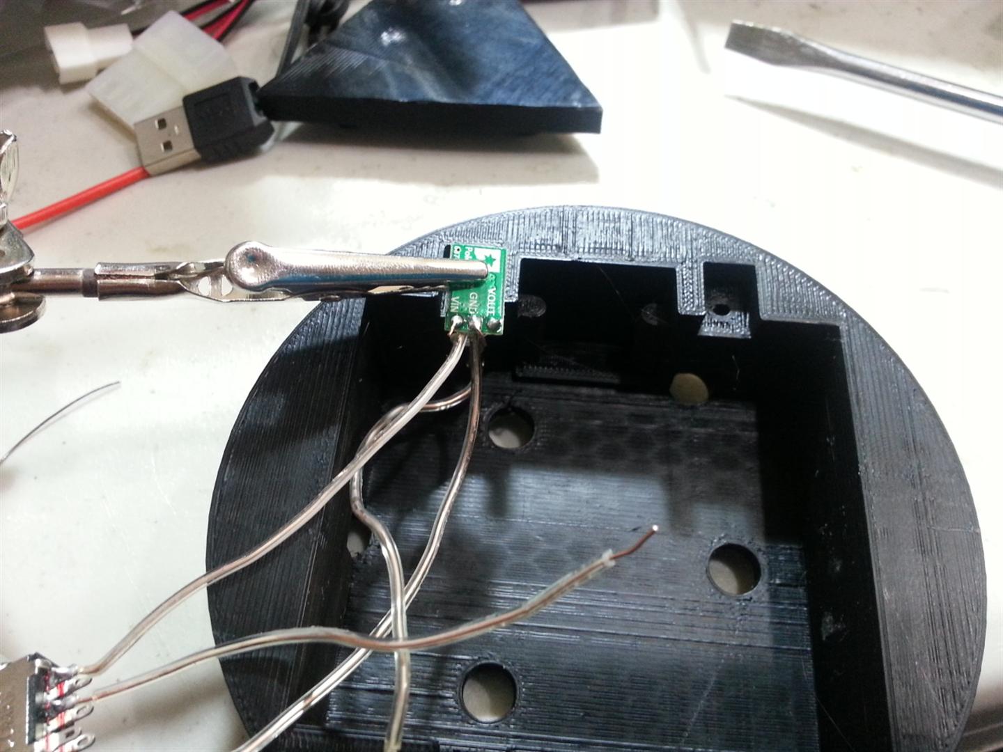
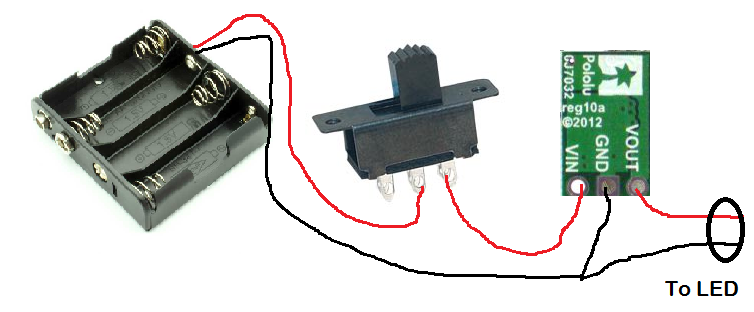 Start by soldering the positive (+) wire to the LEDs to VOUT on the regulator, and solder ~4″ lengths of wire to GND and VIN on the regulator:
The VIN wire will go to the switch and the GND wire will connect to negative (-) of the battery pack along with the negative wire from the LEDs. To make all the connections with the batter pack, twist the wires together:
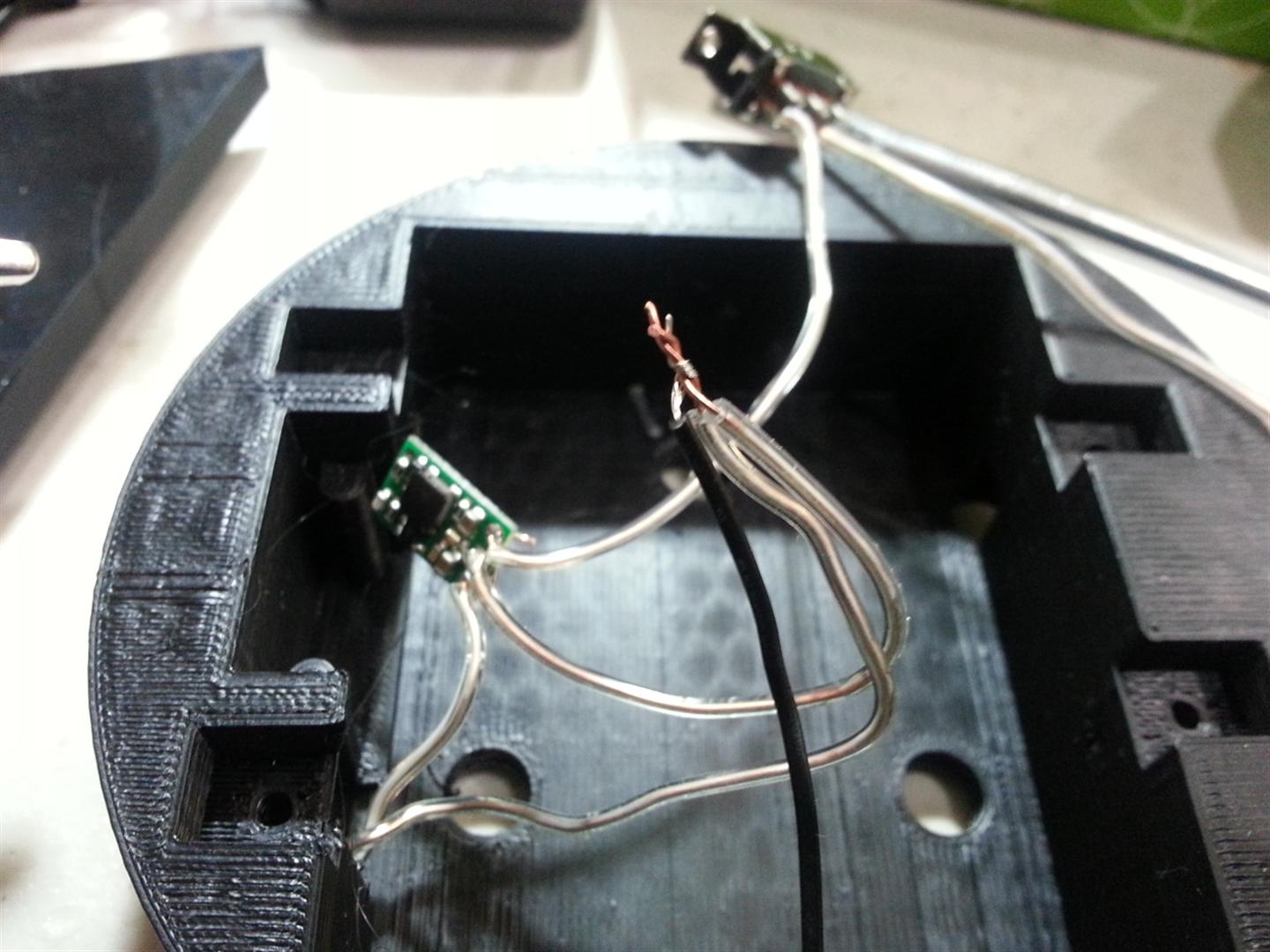 And solder the connection secure:
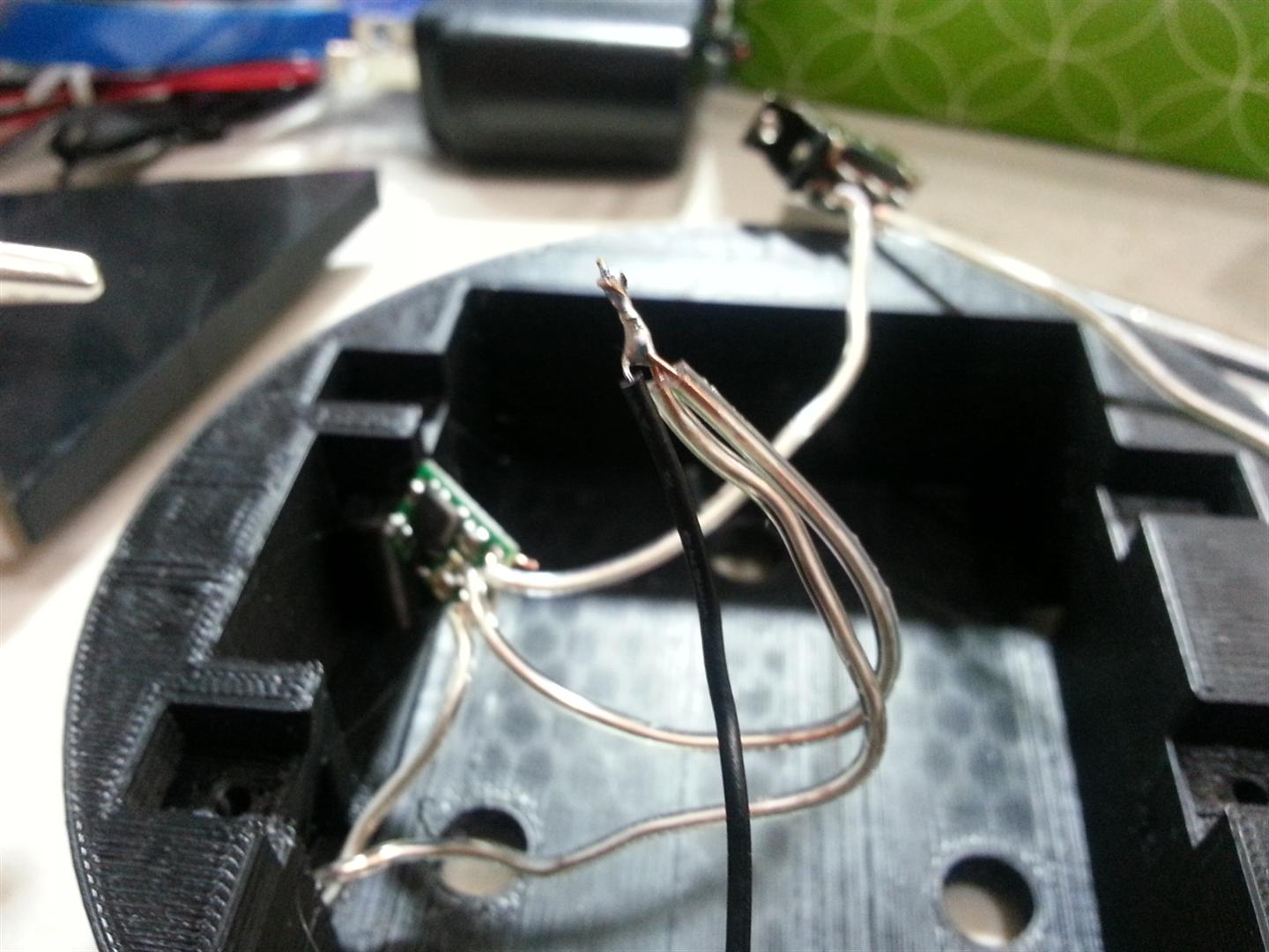 Repeat with the positive connection and then a little electrical tape will insulate the bare wires:
Finally I recommend gluing the batter holder into the base and tucking the regulator and wires along the side:
Assembling the Centerpieces
Assembly is a snap, literally. The main pieces fit together nub and hole style, kind of like Lego pieces. I made the nubs large enough they would fit into the holes with some force and don’t come apart easily. This meant I could build the centerpieces without getting messy with glue.
Start by snapping the side pieces out of the single sheet of plastic that ran through the Silhouette. The design the silhouette carved into the plastic includes straight scored lines with which to break apart the pieces.
Start bending along the scored line.
And snap, another side piece.
Peel back some of the protective wrap on either side and insert 3 side pieces into the top retainer piece. Make sure to leave the side the Silhouette carved facing outwards. You’ll see why later.
Push into top retainer.
Add all 3 sides.
All 3 sides added, and internal protective wrap removed.
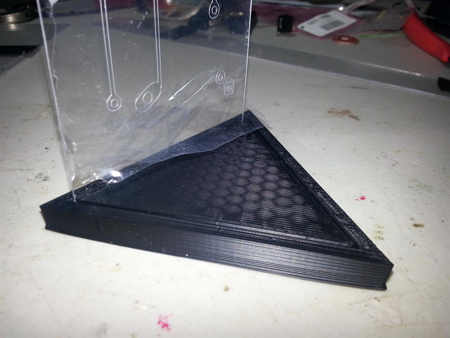
Next the base comes together. First, snap the triangular internal spacer onto the base.
Push the triangular spacer onto the base with some force until it snaps flush.
Perfect.
Then peal back more of the protective wrap on the sides of the centerpiece and slide the retainer ring down the side.
Retainer ring around sides, nubs down.
Flip over and position sides onto base around spacer.

Slide ring down and snap together with base.
Just like the triangular spacer, the retention ring snaps into the base. The compression between the ring and the spacer hold the plastic sides against the base very well. No glue needed.
Almost done, just need to remove the protective wrap.
The protective wrap on the plastic on the side the Silhouette carved has been cut up into pieces. This made removing all the wrap tedious, until I came up with this trick:
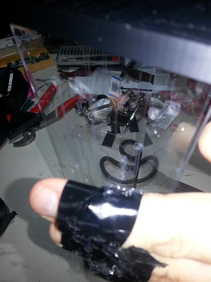
Wrap electrical tape around your fingers sticky side out and ‘stick’ sides repeatedly.
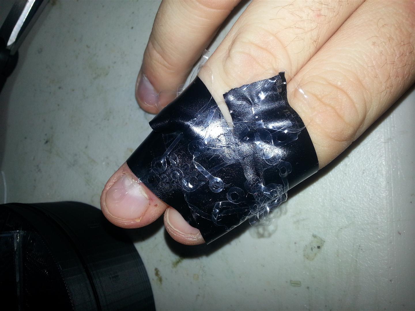
Wrap pieces removed with ease.
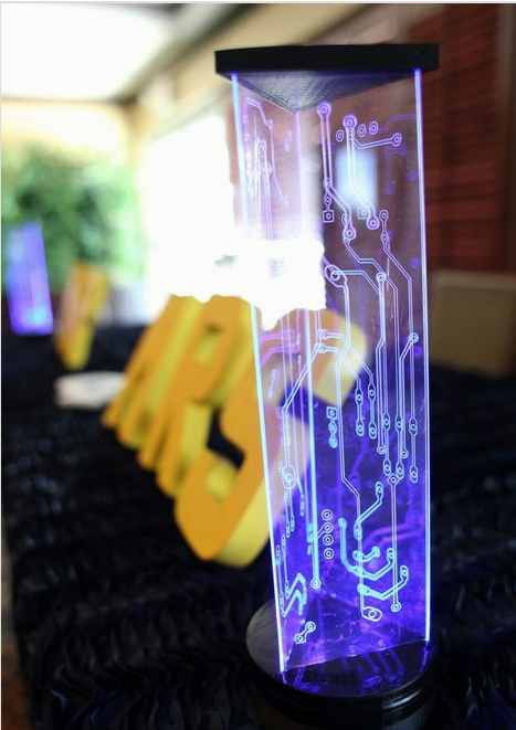
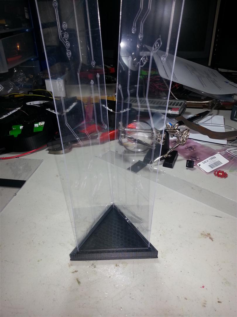
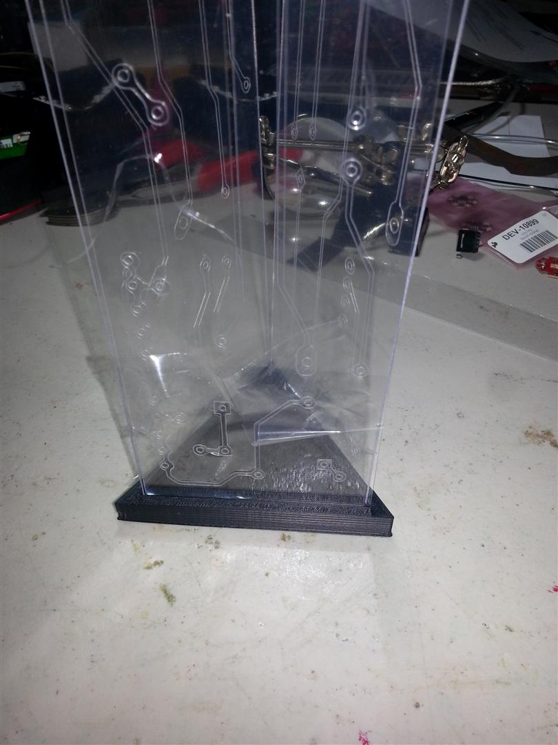
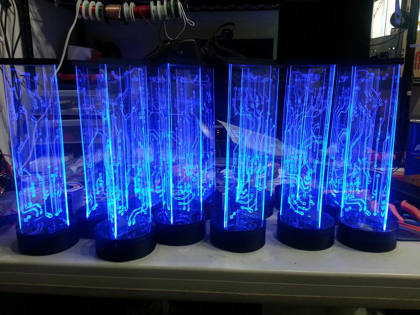
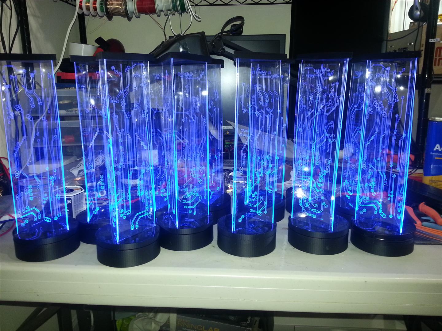
And you are done! Completed centerpieces.
Matching Cake Topper
At the last minute, we used the same technique to make a matching cake topper. This time the design has one side and uses two LED strips in a row. All the pieces snap together like the centerpiece, but a wire runs out to a separate battery pack. We used a 3x AA battery pack and a Pololu voltage booster to give us the needed 12V.
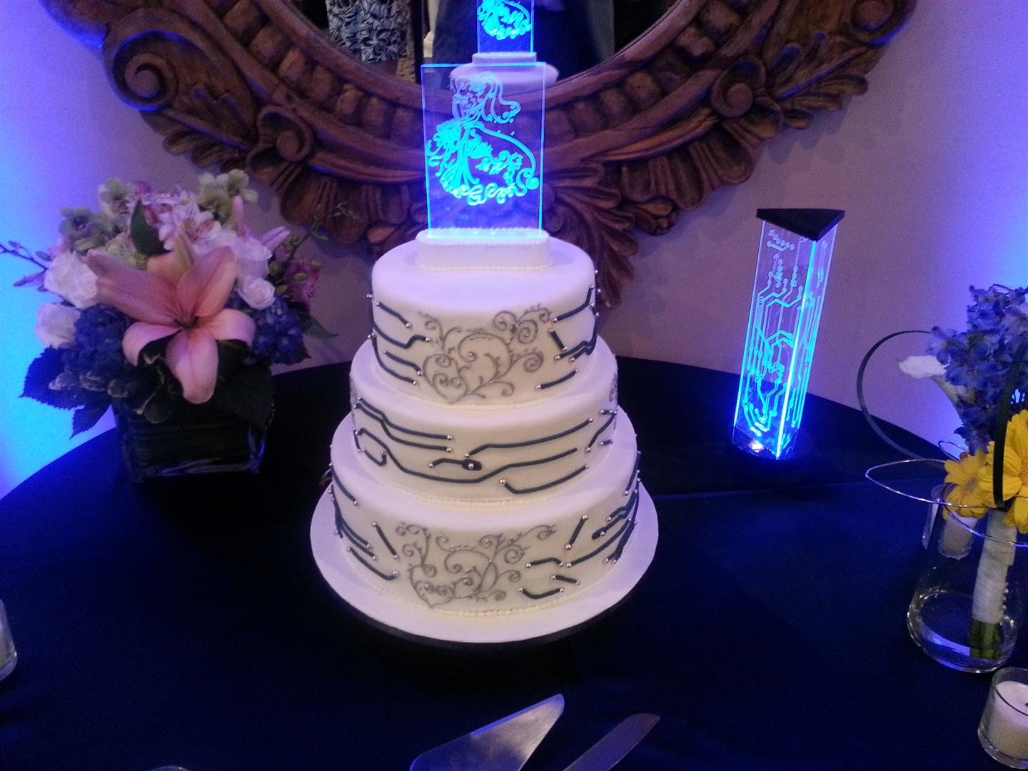
Matching cake Topper.
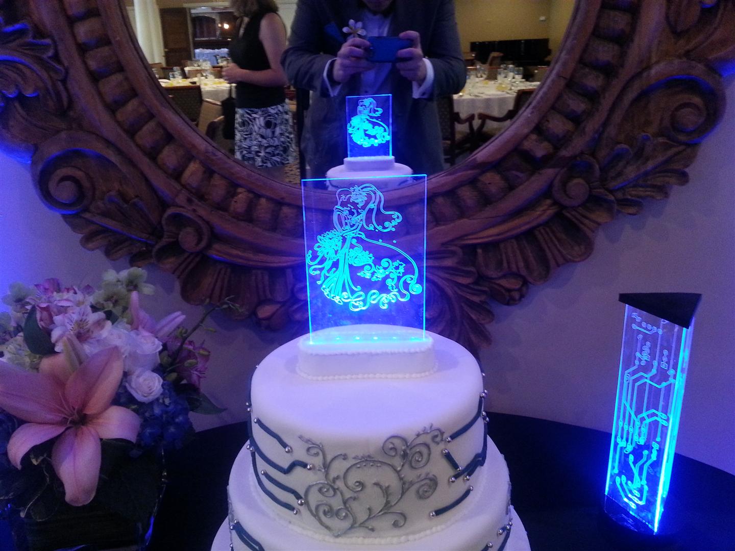
Up close.
