

Part 5 of the tour through Our Geeky Wedding focuses on the clothes we wore for the wedding. Or, technically what we did to the clothes we wore for our wedding. Of course in a wedding with an engineering theme only one thing comes to mind when you think of the attire: e-textiles!
The Plan
Mara and I both decided to design our own clothing for the wedding. Since I knew I’d be ruining improving whatever suit I’d be wearing for the wedding, I knew I couldn’t rent. So I used a suit left over from a buddy’s wedding instead of buying a new one. Mara took customization up a level and designed a dress and bought it from a vendor on the cheap. Both garments were the right price for our geek wedding.
The Technology
We both knew we wanted LEDs and/or EL wire to play a part in the design; however we still were on a tight wedding budget. KISS (Keep It Simple Stupid) and cheap were the main goals as I set out deciding how to design the systems we needed for our attire. Lilypads offer some great options for e-textiles, but I didn’t want to fork out $25 per pop to have a ATMega powered LilyTiny just blink some LEDs. Instead, the $7 ATTiny powered LilyTiny looked much more reasonable. Since it only broke out 4 IO pins, I decided to try using Charleplexing to maximize the number of LEDs it could control.
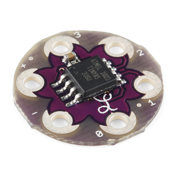
LilyTiny board
The Charlieplexing code I wrote for the LilyTiny (available HERE) enables the individual control 12 LEDs. It runs via a interrupt driven software PWM/plexing routine. I combined this firmware with my Vixeno Vixen python script to create customized light animations powered by the LilyTiny.
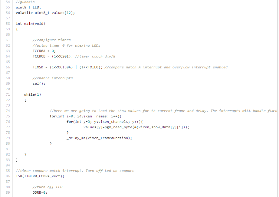
Vixen – Charleplexing code for ATTiny
The flash memory in the ATTiny is large enough to hold about a minutes worth of 12 channel 8 bit information at 10 frames per second. More than enough for some cool custom light animations. Now we had an inexpensive way to add LEDs to our attire.
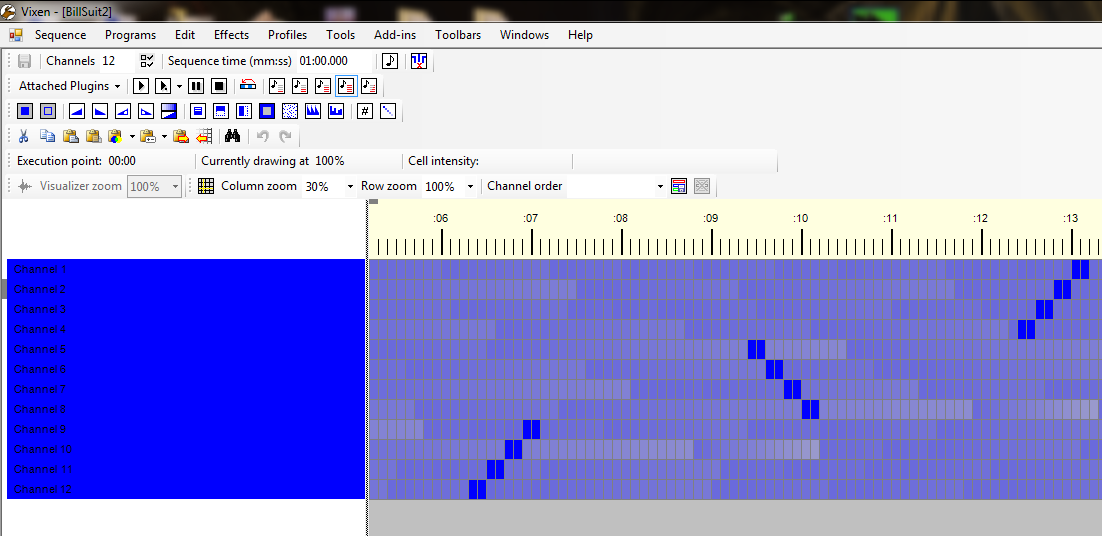
Vixen LED sequence writing
Next was EL wire. I knew I wanted to run EL on one side of my suit, but being a big guy I wanted to avoid bulky inverters in any pockets. Even the bulge from a run-of-of-the-mill 2x AA battery pack inverter would stick out stick out like a sore thumb. I already planned to have a ‘master battery’ in a pants pocket run both the LEDs and EL wire, but i couldn’t find an appropriately sized inverter. All the offerings from the usual players were for large 12V inverters meant to run meters upon meters of EL wire. I needed ~8V input, small size and only needed to run about 5′ of wire. Since nothing fit the bill, I decided to make my own, in a sense.
Custom Inverter
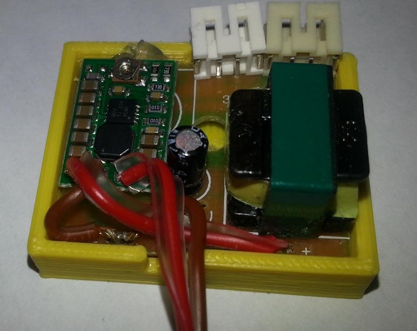
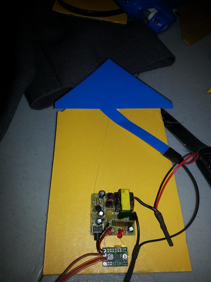
I started with the really inexpensive Sparkfun EL battery pack/inverter. I removed the shell and took out just the inverter bit. I reverse engineered the design enough to figure out how to bypass the on-board microcontroller that generated the On/Off/Blink function and just keep the inverter circuit powered indefinitely.

The brown wire soldered to the exposed test points will keep the inverter running
This also let me cutoff the large push button power switch.
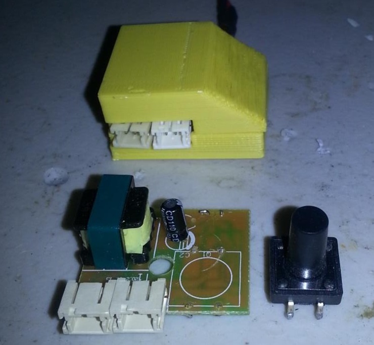
Removing the button saves a lot of space
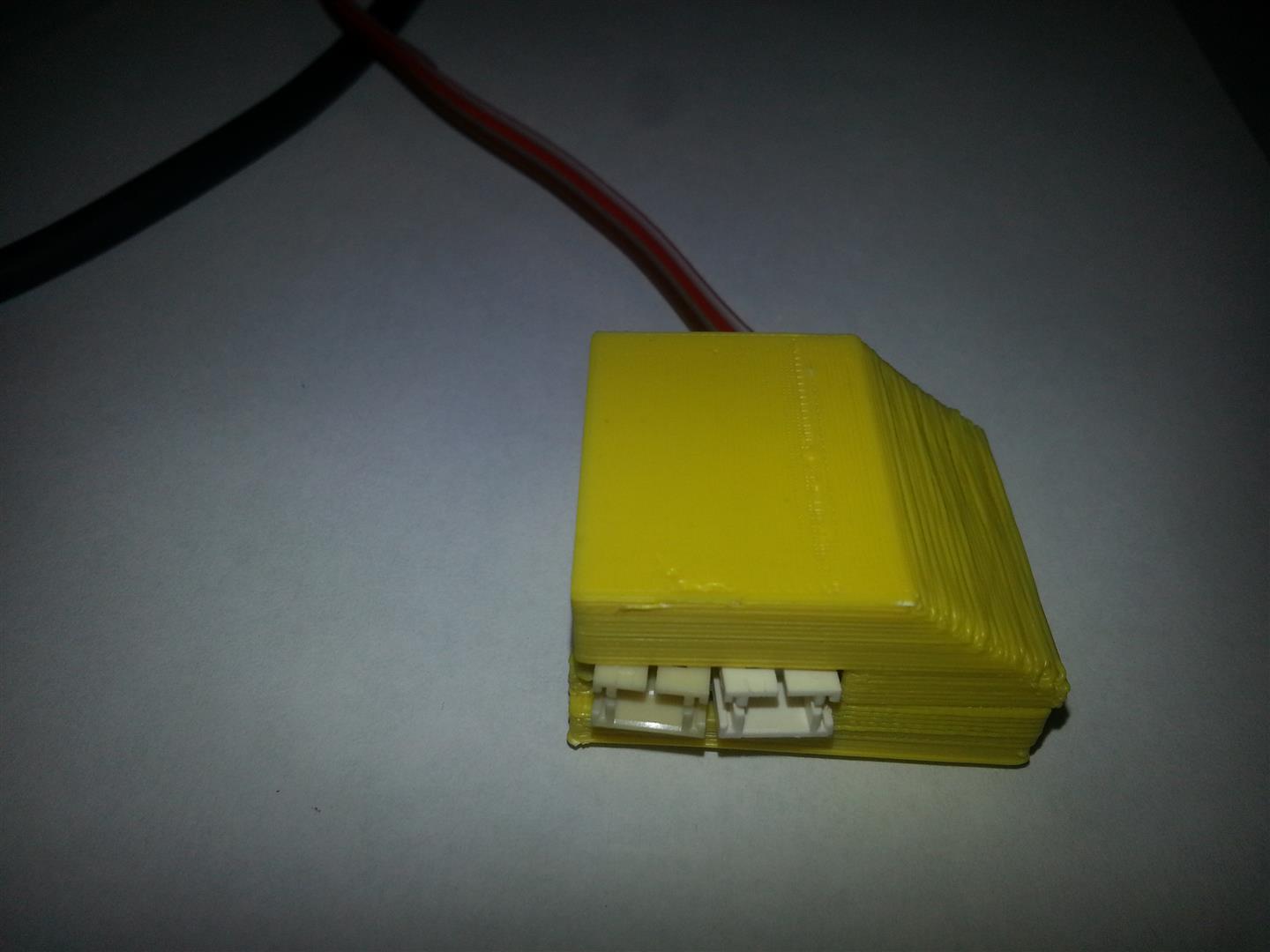
I took a few measurements, opened up AutoDesk and whipped up a simple case design to house just the inverter PCB. Since the inverter was designed to accept 3V, I left just enough room in the custom enclosure to squeeze in a Pololu voltage regulator.
Inverter with voltage regulator
With the battery springs and push button removed, I had my small profile inverter that would run off of the 8V from my battery pack.
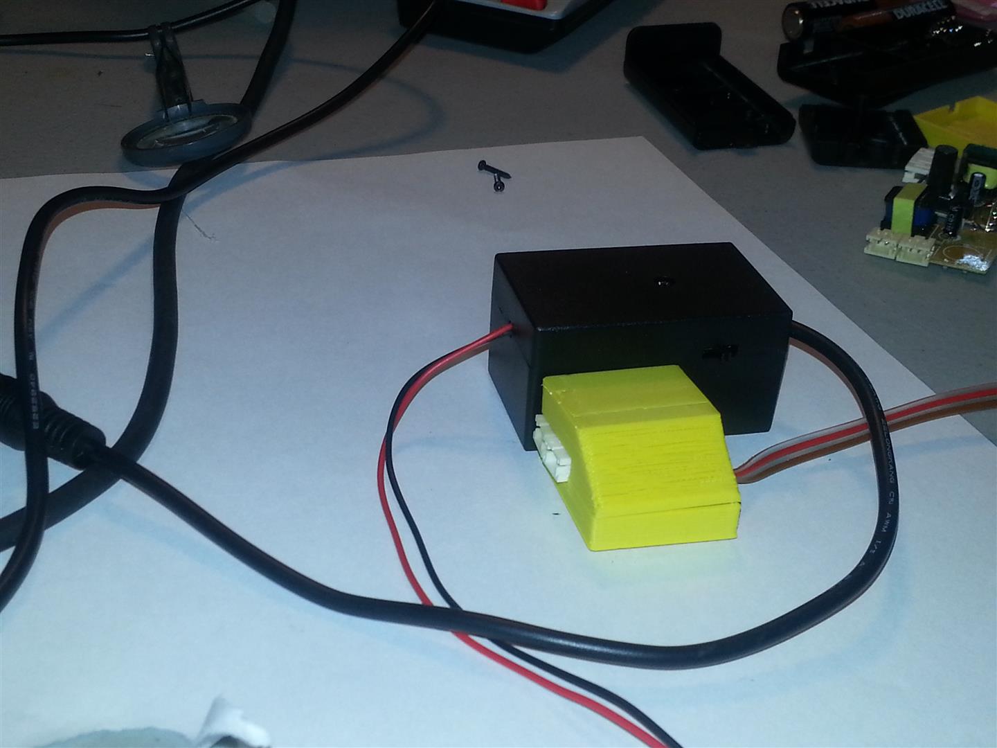
Size compared to COTS 12V inverter
Speaking of the battery pack, I knew I needed something that energy dense to run my suit all night but still light weight and small profile. Also, free would be nice. That limited me to what I had on hand, which just happened to be a bunch of 18650 Li-Ion cells, the same ones used in our custom centerpieces. I was running short on time so I drafted and 3D printed a simple protective case for the batteries, threw in a Li-Ion protection board, wrapped the whole thing up in electric tape and called it a day.
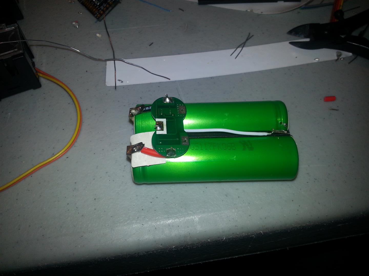
Cells wired in series with protection board
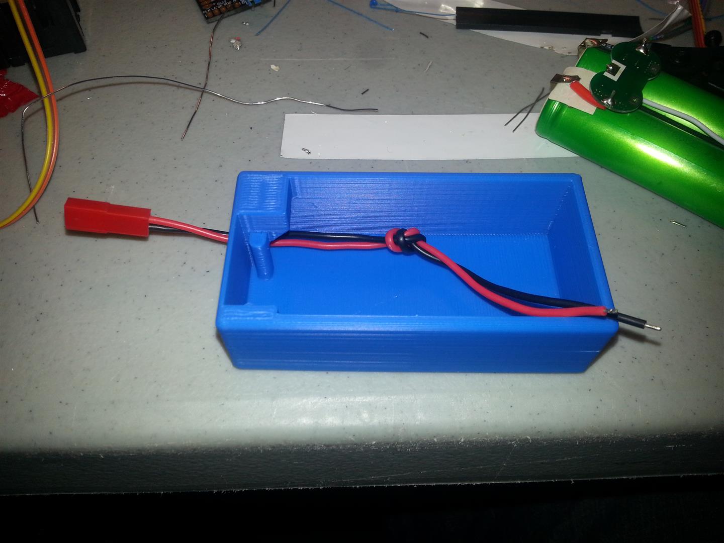
Battery box with connector
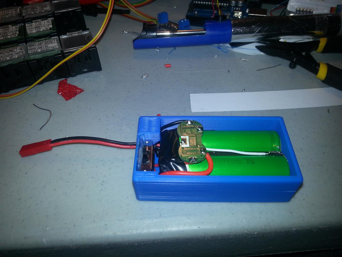
Batteries, switch installed
At 2.2AH @ 8.4V, one pack lasted just long enough to make it through my reception. I also used the same battery design to power the display used in our geeky circuit ceremony.
The Design
The idea I had for my suit was to create ‘circuit traces’ on the left side with the EL wire. I took a picture with the suit and sketched out a rough idea. Using my sketch as a guide, I cut the EL wire into various lengths and terminated one end of each bit with thin enameled magnet wire, which was a tricky proposition. I started by removing the enamel with a dremel, soldering one wire the the core conductor, shrink tube sealing the connection, soldering another wire to the outer conductor and shrink tube sealing the whole end. I choice enameled magnet wire because I had it on hand and it seems small/flexible enough to route around my jacket with little effort.
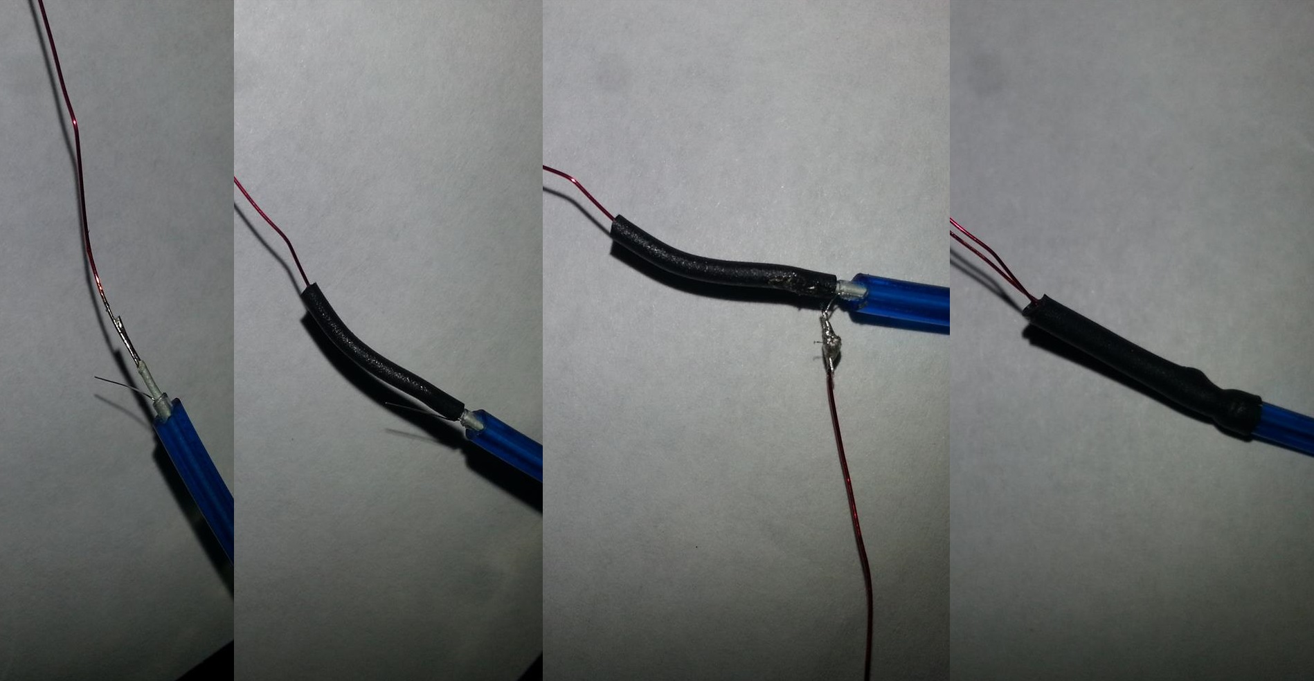
EL termination steps
I took some sewing pins and laid out my design with the EL wire. I used the terminated end as an anchor point by threading the magnet wire through the suit.
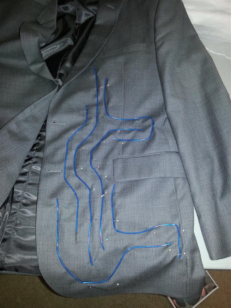
First design held by pins
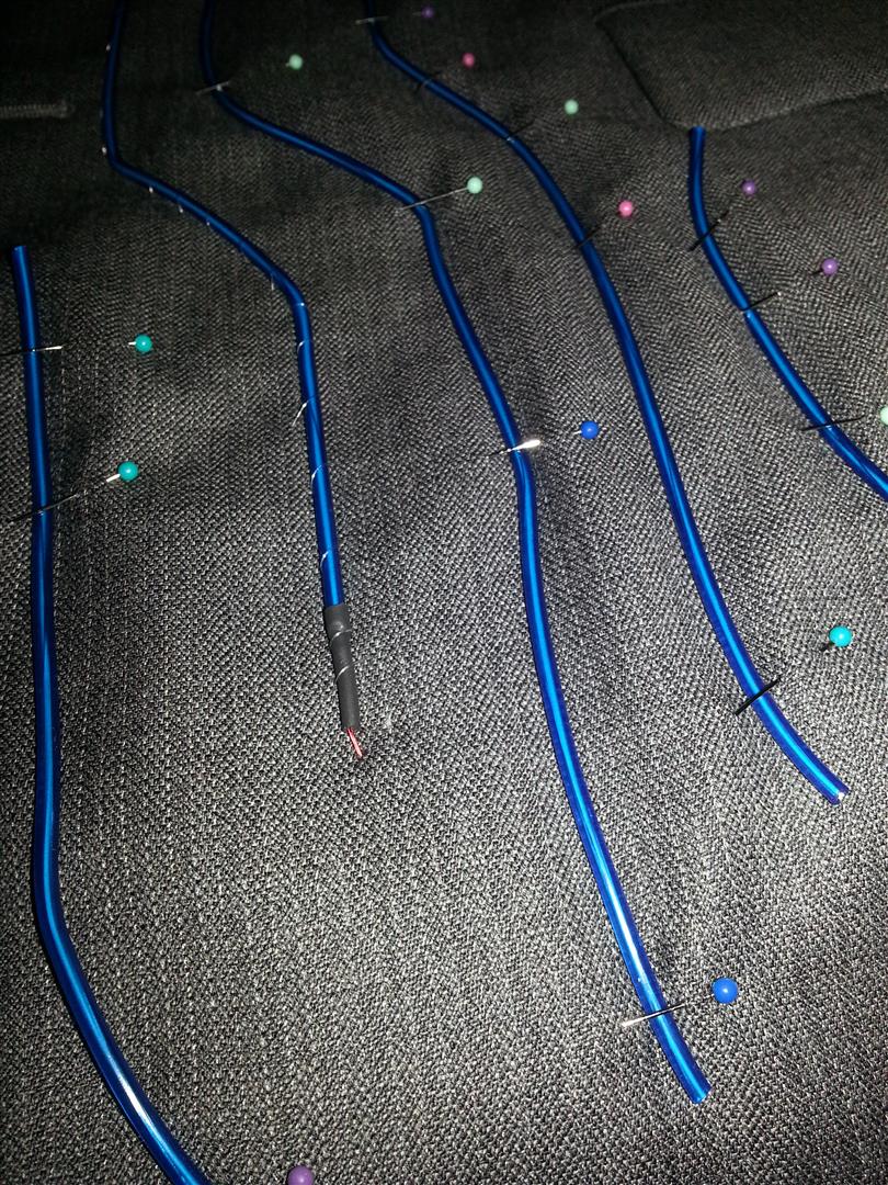
Closeup

Threading wire

Anchored
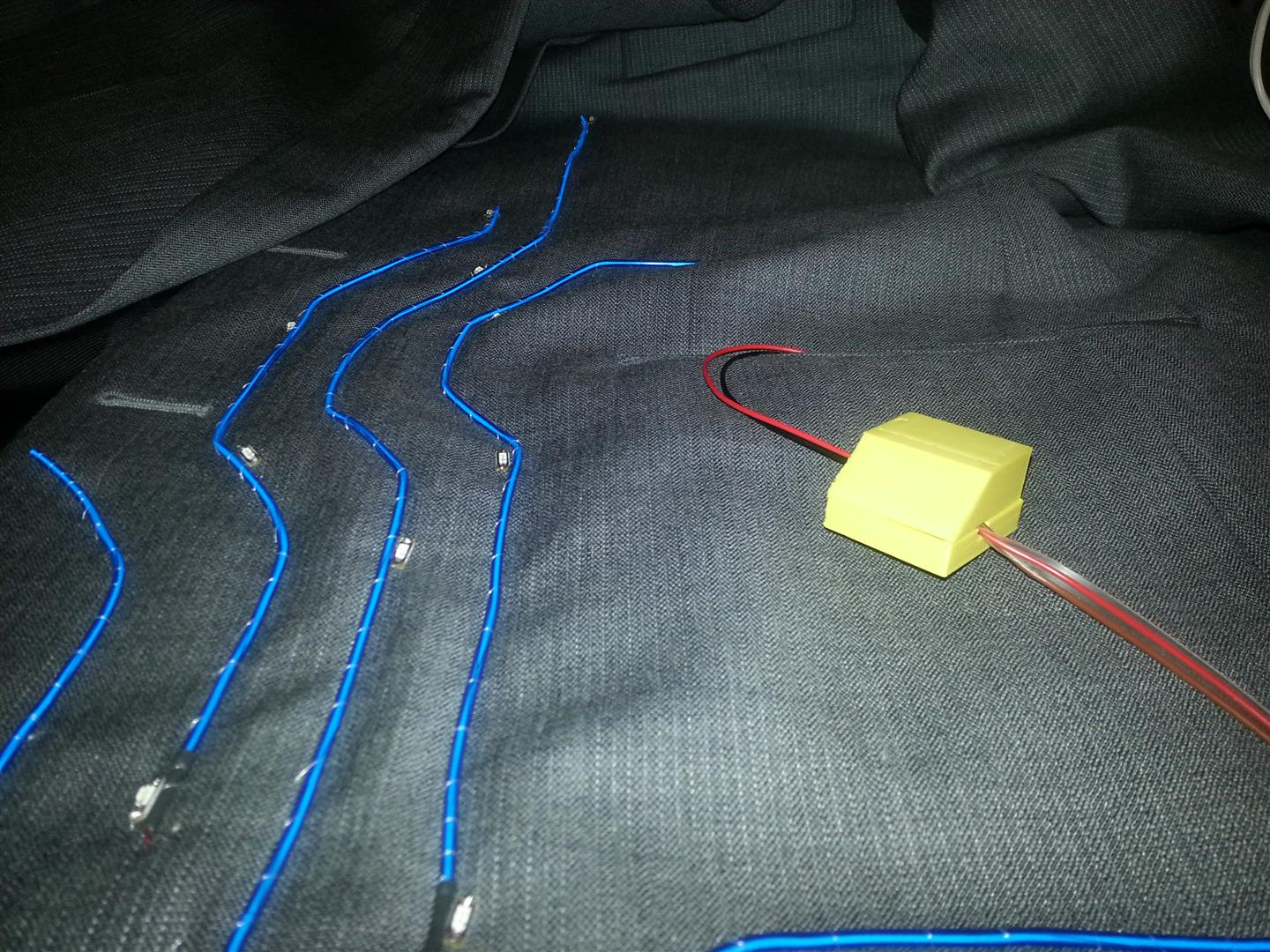
Then came the sewing, LOTS of sewing. I used clear sewing thread to secure the EL wire to the suit. It took about 2 afternoons to sew it all down. Afterwords, I twisted all the enameled wire together and brought the bundle to the exterior pocket.
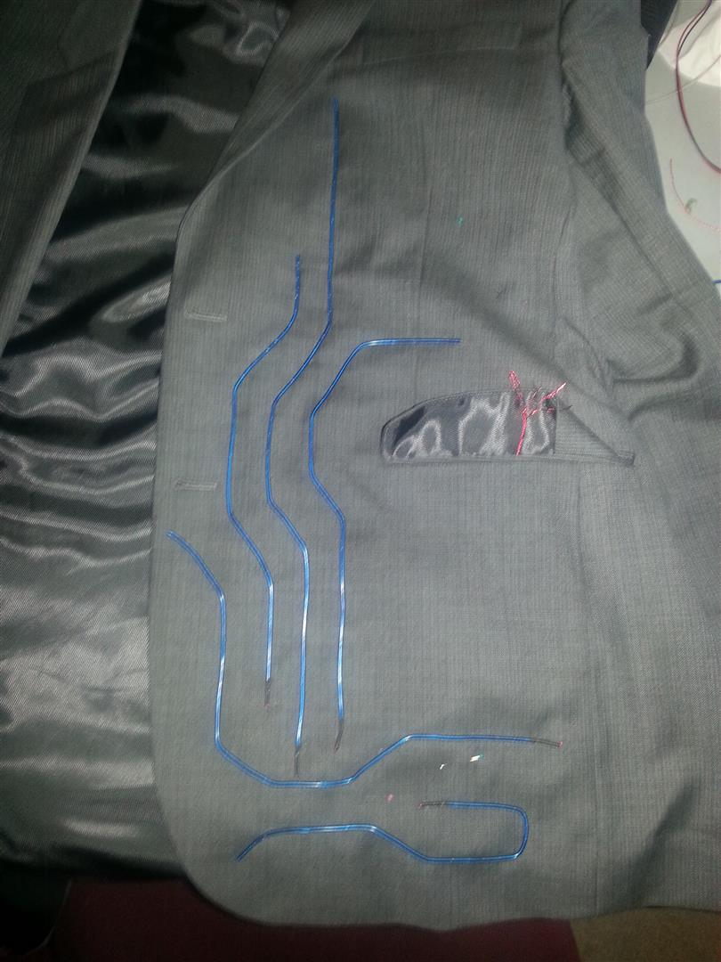
All done with EL
Next came the LEDs. My idea was to match blue LEDs with the blue EL wire and create an effect of electricity ‘flowing’ through the wires. Since I had 12 LEDs to work with off one LilyTiny, I split them up into 3 groups of 4. I placed a group of 4 along 3 of my EL wires. Only downside to Charlieplexing is the complicated wiring, so I drew a picture to help me out.
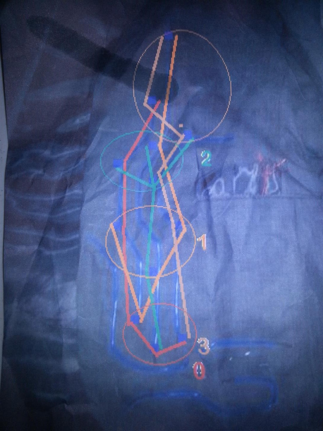
Wiring plan for Charleplexing
The colors in the diagram match the 4 color wires I used. If the LED with a certain color wire running to it (let’s say RED) fell into a matching color circle (RED) that meant the wire was soldered to the positive side of the LED. Otherwise it went to negative. This made it easy to wire the charleplexing grid and match which LED channel was where.
I used strands from a rainbow ribbon cable to connect the LEDs. Since all but a few junctions required a wire in and out I’d take two striped wires and twist them together. I’d solder the twist and use a needle to poke it through the jacket, finally soldering it to the LED. In the end I had my LEDs along my EL wire ‘traces’.
EL wire and LEDs
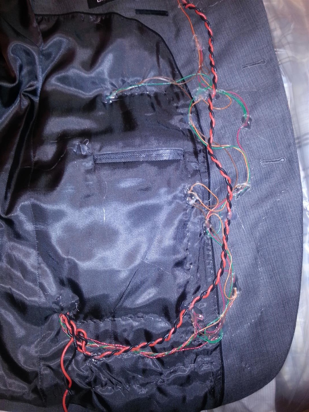
Behind the suit
I used a gluegun to secure the points where the wire pierced the jacket and other various places to keep it neat.
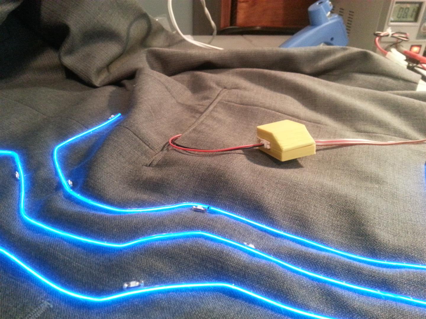
Quick test of the EL wire
I soldered the 4 wires to the LilyTiny and glued that to a piece of cardboard. I added a Pololu voltage regulator to drop battery voltage down to 5V for the LilyTiny.
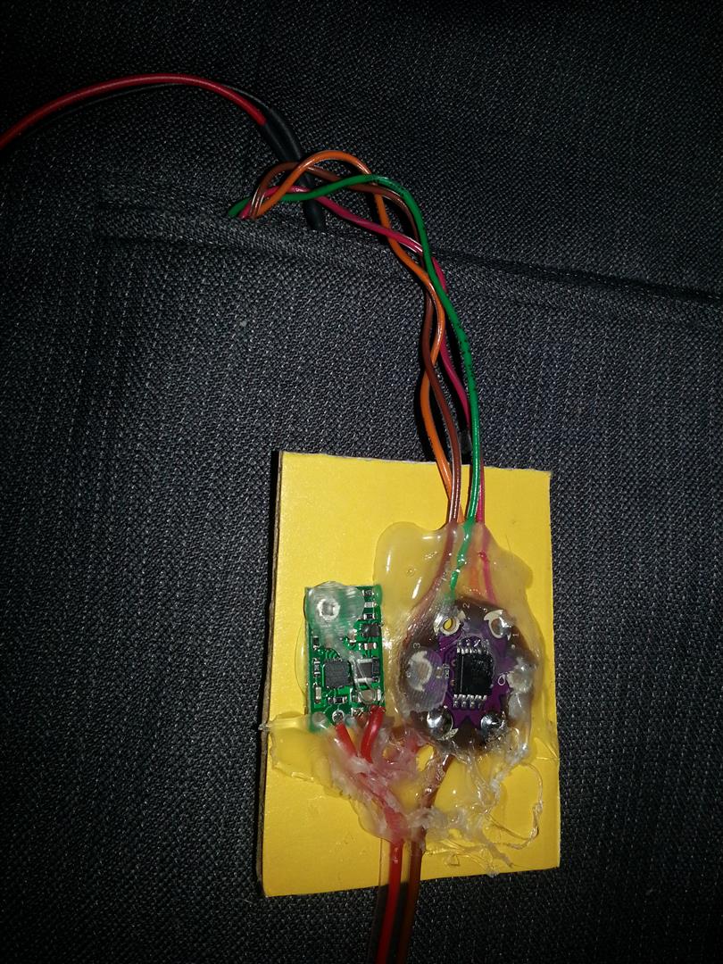
LilyTiny and regulator
But I wasn’t done there. I had an idea for another element to the design, an EL handkerchief square in the breast pocket. This element ended up causing me the most grief. I started by taking a blue EL panel from Sparkfun and trimming it to fit in the pocket. The Sparkfun EL inverter wouldn’t power the square, but a similar model from Adafruit seemed to do the job. Just like the Sparkfun inverter, I reversed engineered the Adafruit inverter and soldered a jumper to keep the inverter part on all the time. I glued it along with a voltage regulator and the trimmed EL panel to another piece of cardboard.
EL napkin Mod 1
However it seemed trimming the EL panel caused it’s power consumption to increase. The Adafruit inverter would overheat and shutoff after a few minutes. I trashed the design and started again. Not taking any chances I minimized the amount of material removed from the EL panel and switched to a beefy 12V inverter from Adafruit, mated with a Pololu boost regulator to supply the 12V. I tucked the inverter down into an internal chest pocket and that seemed to minimize it’s bulge.

Mod 1 vs Mod 2
I had Mara slice up some vinyl circuit traces on her Silhouette Cameo craft cutter and laid them out on the EL ‘napkin’.
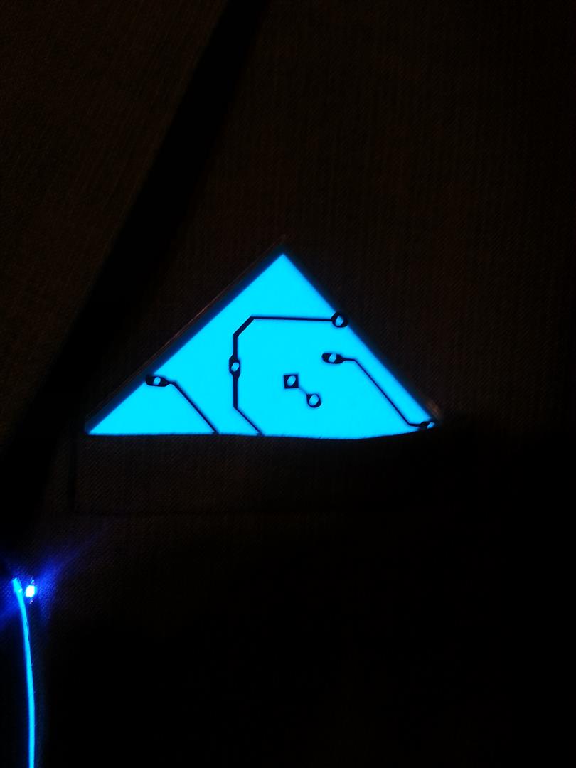
EL Napkin
And put it all together:

Geek suit
Video demo of the suit, with LED pattern running.
Next up is Mara’s dress. She decided not to include any EL elements, but she did want LEDs. Using the same design as my suit, she took 2 LilyTinys, programmed them with a Vixeno sequence and wired up two charlieplexing displays.
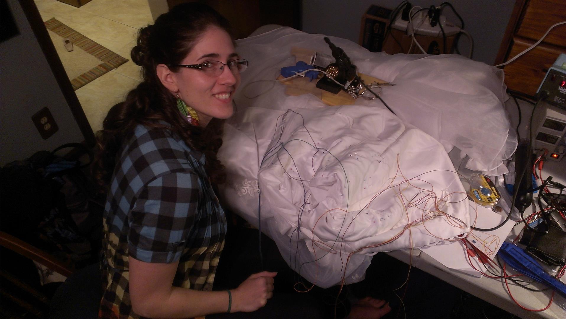
Soldering her wedding dress, days before the wedding
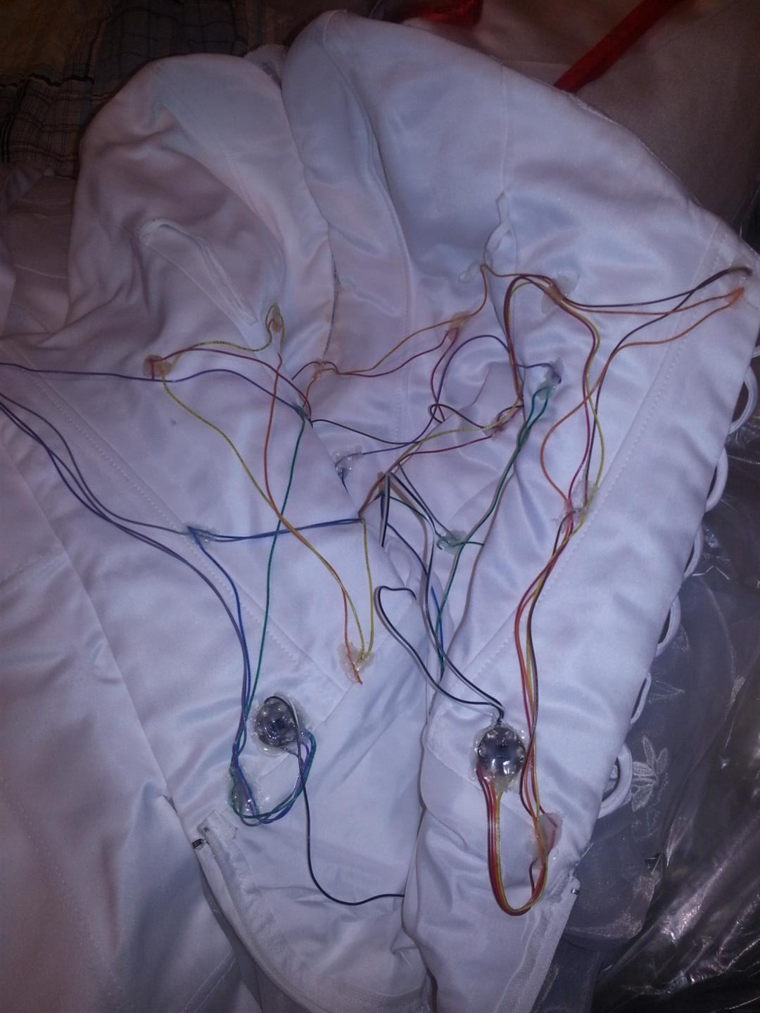
LilyTiny’s flanking the inside of the dress
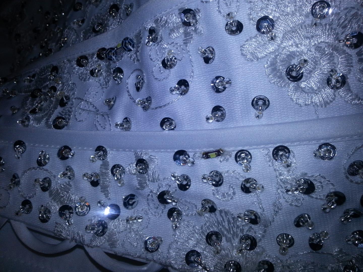
LEDs hide nicely
For power, we glued a Pololu boost regulator to a 2x AAA battery pack. With no other ideas on where to hide said battery pack, we tied it to a second garter she wore throughout the night.
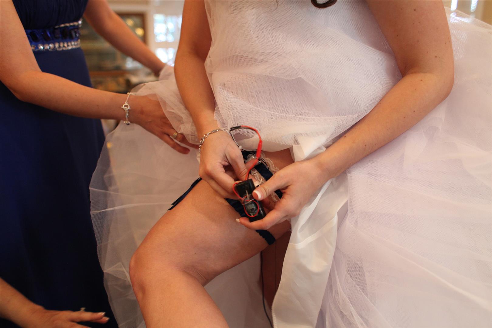
Power garter
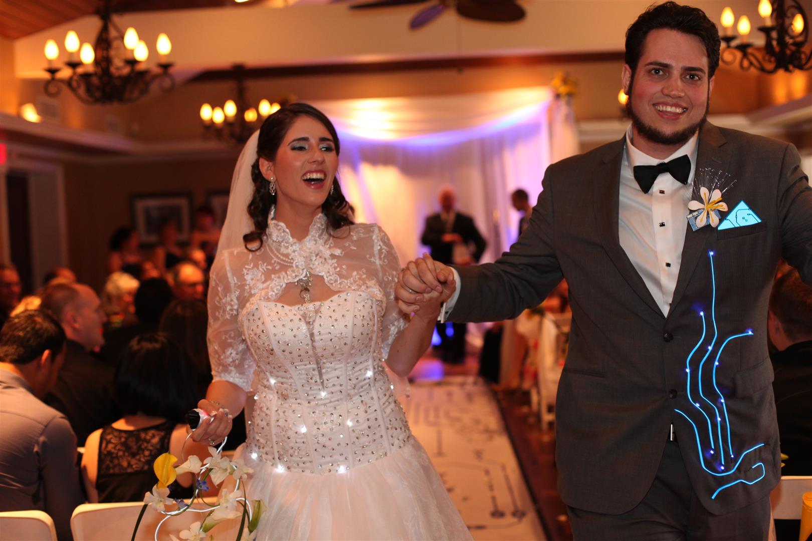
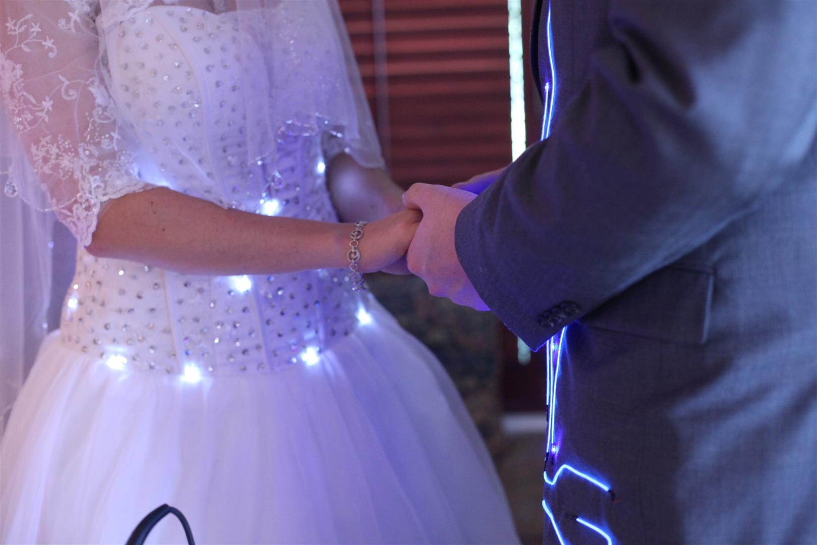
Both pieces turned out to be a big hit at our wedding. Both my suit and her dress ran all night with no problems, and our guests couldn’t stop complementing us on how well them came out!

At the alter
Up close

Trackbacks / Pingbacks